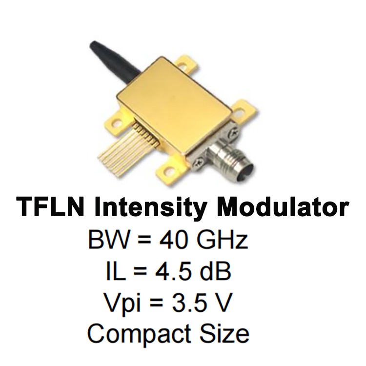
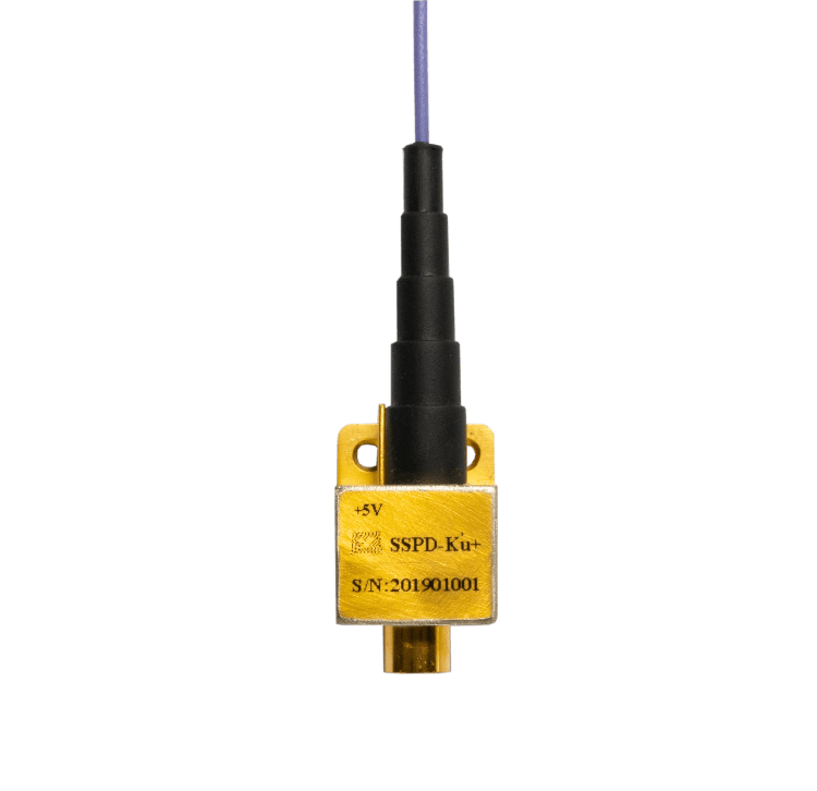
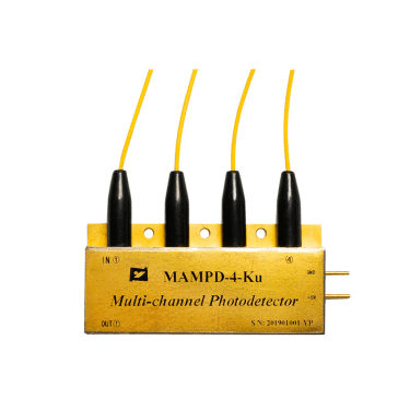
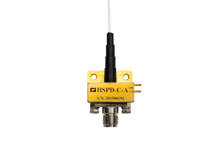
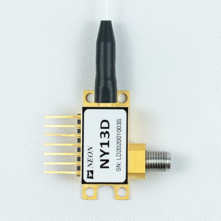
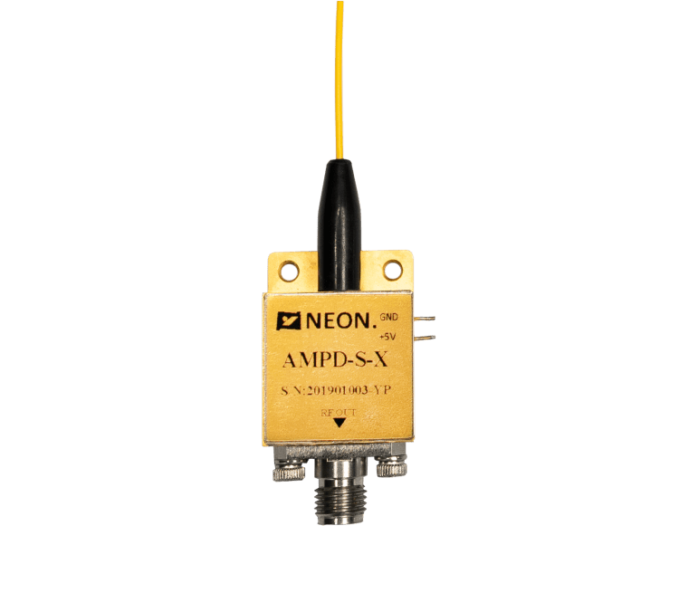
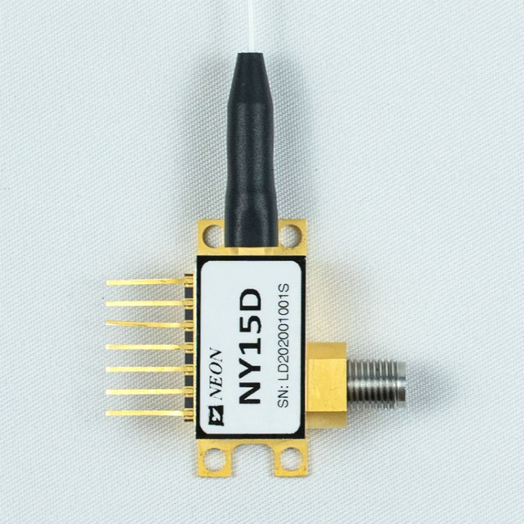
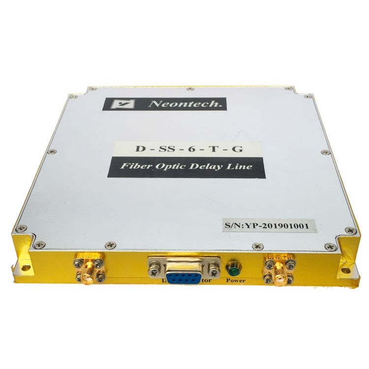
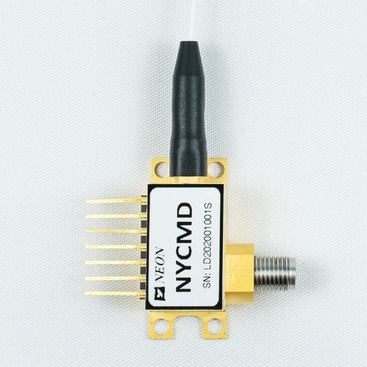
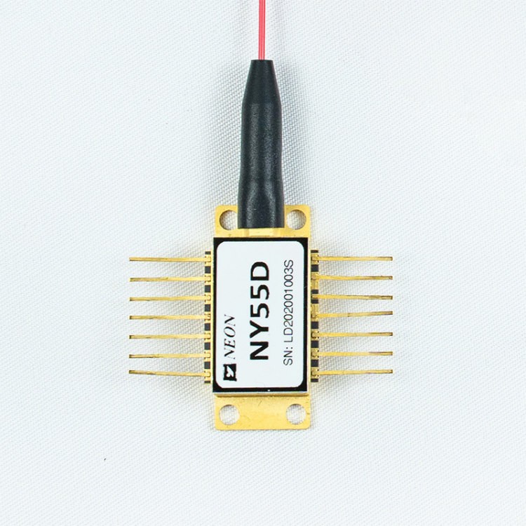
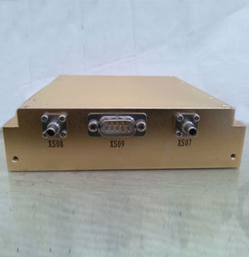
TFLN Intensity Modulator (No Light Source)
- High RF Bandwidth up-to 40 GHz
- Low half-wave voltage down-to 2 V
- Low insertion loss down-to 4.5 dB
- Small device size
Attachment
The thin-film lithium niobate (TFLN) intensity modulator is an exceptional opto-electric converter device, which was developed in-house and showcased unparalleled performance. This device features thermal-optic bias control interface and is manufactured using advanced coupling and micro-electronic processes, and realizes high opto-electric conversion efficiency on TFLN. Compared to other commercial bulk lithium niobate-based modulators, our products provide superior characteristics on half-wave voltage, stability, and device size, significantly enhancing critical performance in digital optical communications and telecommunication networks.
Absolute Maximum Ratings
Working over maximum ratings could significantly reduce device reliability and cause irreversible damage.
| Parameters | Symbol | Min. | Max. | Unit |
| RF Input Power | Sin | – | 23 | dBm |
| RF Swing Voltage | Vpp | -4.465 | +4.465 | V |
| RF RMS Voltage | Vrms | – | 3.16 | V |
| Optical Input Power | Pin. max | – | 20 | dBm |
| Heater Bias Voltage | Vh | 0 | 5 | V |
| Storage Temperature | Ts | -40 | 85 | ℃ |
| Relative Humidity(no condensation) | RH | 5 | 90 | % |
Specifications
| Category | Parameters | Symbol | Unit | Performance | |
| Optical Features | Operating Wavelength | λ | nm | X2: C | |
| ~ 1550 | |||||
| Optical Extinction Ratio(@ DC) | ER | dB | ≥20 | ||
| Optical Return Loss | ORL | dB | ≤-27 | ||
| Optical Insertion Loss | IL | dB | Max: 5.5Typ: 4.5 | ||
| Electrical Features | 3dB Bandwidth (from 2 GHz) | S21 | GHz | X1 : 2 | X1 : 4 |
| Min: 18Typ: 20 | Min: 36Typ: 40 | ||||
| RF Load | Rm | Ohm | 50±10 | ||
| RF Vπ(@ 50 KHz) | Vπ | V | X3: 5 | X3: 6 | |
| Max: 3.0Typ: 2.5 | Max: 3.5Typ: 3.0 | ||||
| Heater Resistance | Rh | Ohm | 220±10 | ||
| Heater Pπ (@ DC) | Pπ | mw | ≤50 | ||
| RF Return Loss ( 10 MHz to 40 GHz) | S11 | dB | ≤-10 | ||
| WorkCondition | Operating Temperature* | TO | ℃ | -20~70 | |
*Customization is available.
| Category | Parameters | Symbol | Unit | Performance | |
| Optical Features | Operating Wavelength | λ | nm | X2 : O | |
| ~1310 | |||||
| Optical Extinction Ratio(@ DC) | ER | dB | ≥20 | ||
| Optical Return Loss | ORL | dB | ≤-27 | ||
| Optical Insertion Loss | IL | dB | Max: 5.5Typ: 4.5 | ||
| Electrical Features | 3 dB Bandwidth (from 2 GHz) | S21 | GHz | X1 : 2 | X1 : 4 |
| Min: 18Typ: 20 | Min: 36Typ: 40 | ||||
| RF Load | Rm | Ohm | 50±10 | ||
| RF Vπ(@ 50 KHz) | Vπ | V | X3 : 4 | ||
| Max: 2.5Typ: 2.0 | |||||
| Heater Resistance | Rh | Ohm | 220±10 | ||
| Heater Pπ(@ DC) | Pπ | mw | ≤50 | ||
| RF Return Loss (10 MHz to 40 GHz) | S11 | dB | ≤-10 | ||
| WorkCondition | Operating Temperature* | TO | °C | -20~70 | |
*Customization is available.
Package and Pins (Unit: mm)
Working over maximum ratings could significantly reduce Die reliability and cause irreversible damage.
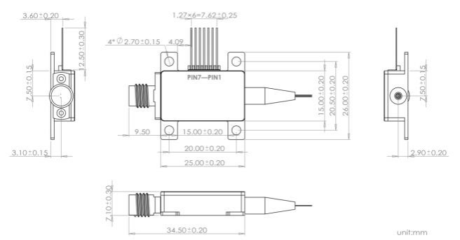
| PIN | Symbol | Description |
| 1 | MPD0+ | MPD0 anode (GND) |
| 2 | MPD0- | MZ modulator input optical power monitor MPD0 cathode |
| 3 | Heater+ | Heater bias positive electrode |
| 4 | Heater- | Heater bias negative electrode |
| 5 | MPD1 + | MPD1 anode (GND) |
| 6 | MPD1- | MZ modulator output optical power monitor MPD1 cathode |
| 7 | – | N/A |
| RF | RF connector* | 2.92mm connector |
| In | Input fiber | FC/APC, PMF |
| Out | Output fiber | FC/APC, PMF |
* Customizable 1.85mm connector.
S21 & S11 Measurement (Typical)

Figure 1: S21

Figure 2: S11
Ordering Information
P/N: NY – X1X2 6PPBM X3 1
| Optional Model | Description | Optional Code | |
| X1 | RF 3dB Bandwidth | 2 or 4 | |
| X2 | Working Wavelength | O or C | |
| X3 | RF Vπ | 5 or 6 for C-band | 4 for O-band |
Product Description: LiNbO3 TFLN intensity modulator device, polarization maintaining fiber as optical input and output.
Contact Information
Email:sales@neoncq.com
Address:16/F, Building L, Gaoke Headquarters Square, NO.64 Huangshan Avenue, Yubei, 401123, Chongqing,China
Statement
NEON reserves the right to make changes without further notice to any products or data herein to improve reliability, function, or design. Information furnished byNEON is believed to be accurate and reliable. However, NEON does not assume any liability arising out of the application or use of this information, nor the application or use of any product or circuit described herein, neither does it convey any license under its patent rights nor the rights of others.


