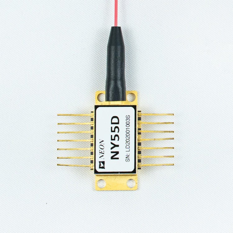
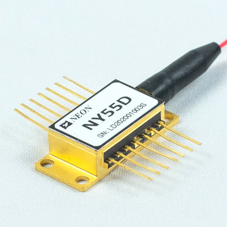
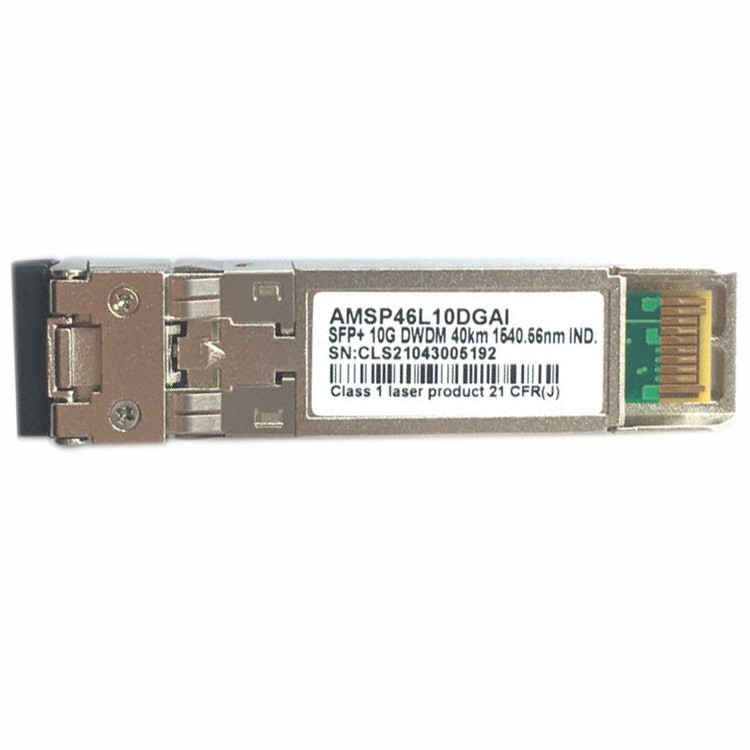
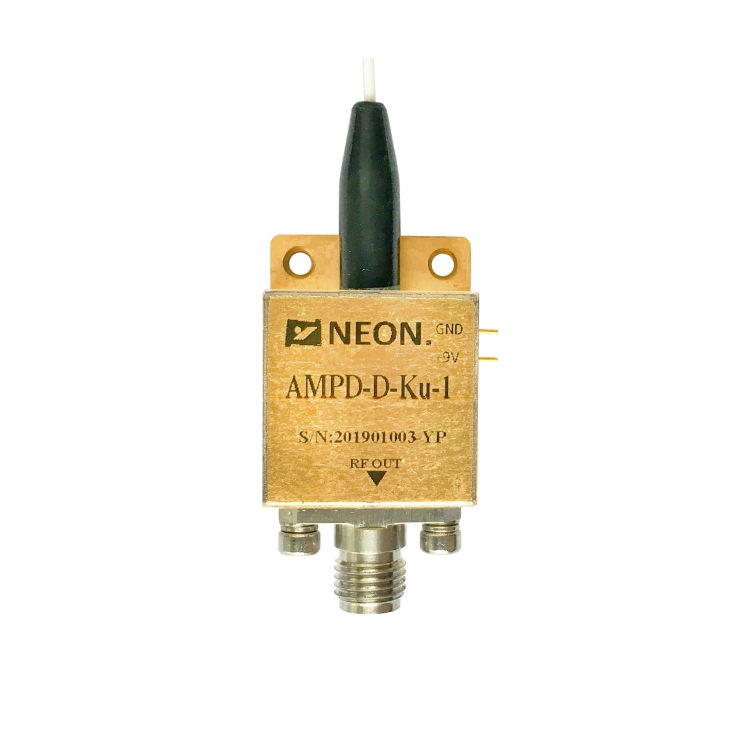
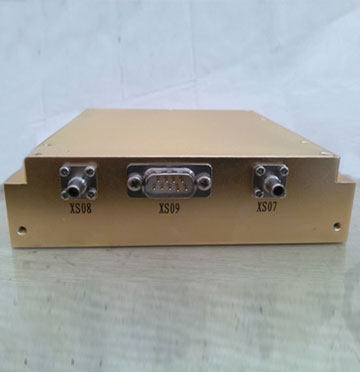
NY55D Series High Power DWDM DFB Laser
- NY55D series laser component is characterized for use as a wavelength selected, high-power optical source in combination with an external modulator in CATV and DWDM networks, especially for super trunking and distribution. Selected wavelengths comply with ITU Grid recommendations, both in range and in channel definition.
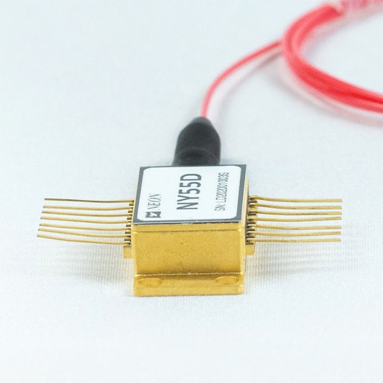
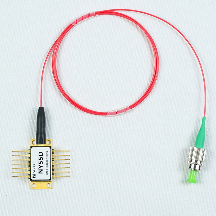
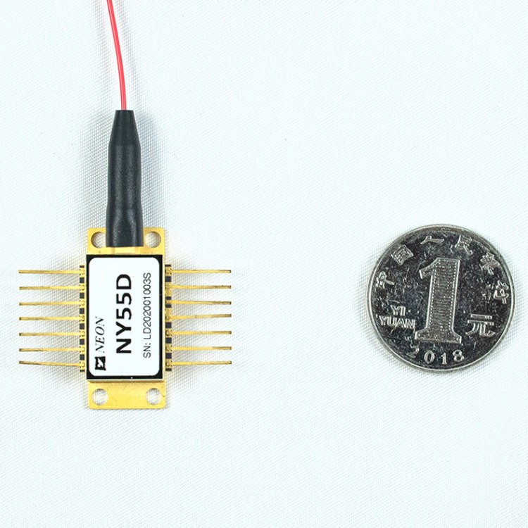
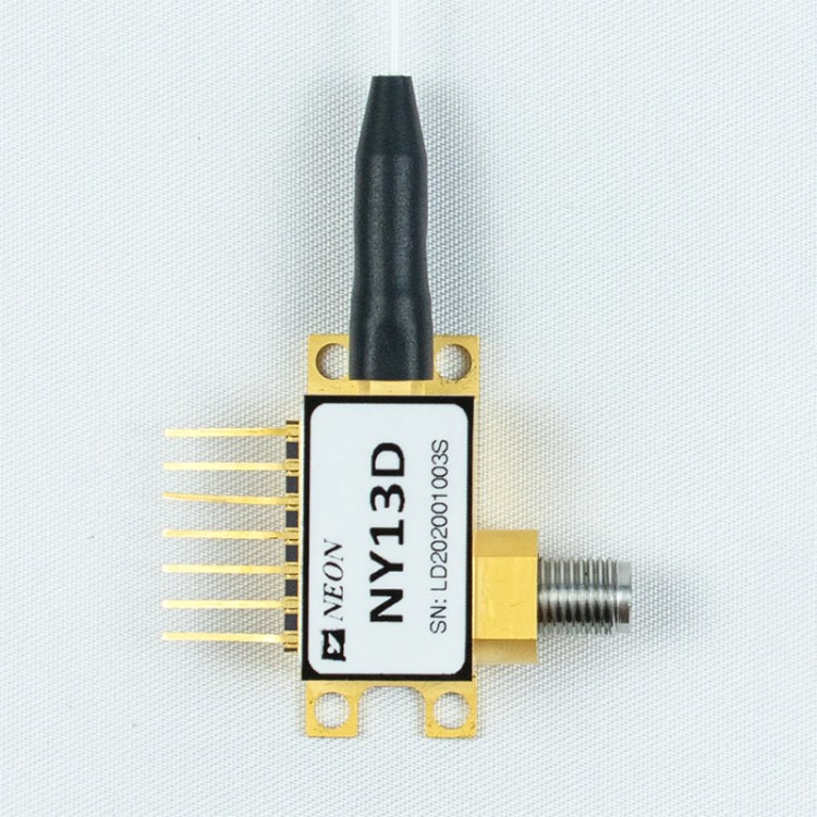
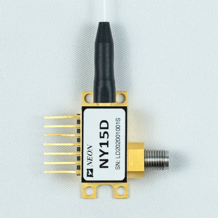
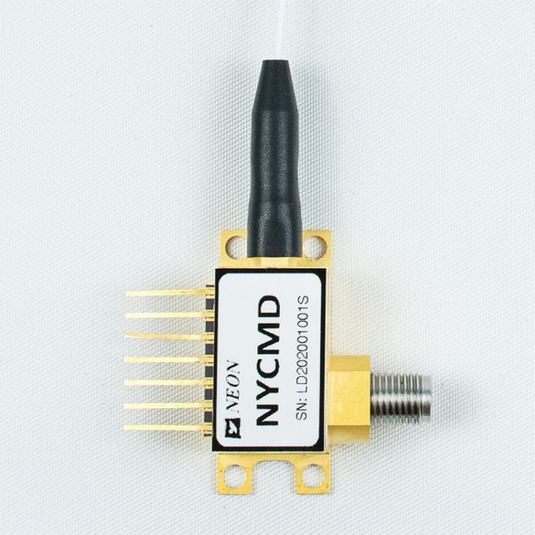
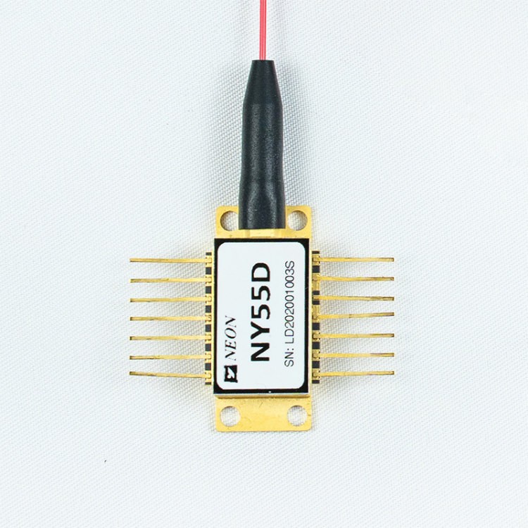
- NY55D series is equipped with polarization maintaining (PM) fiber and DC-coupled with a built-in TEC, thermistor, and monitor photodiode. The device is mounted in a 14-pin, OC-48 pin-out compatible butterfly package with the optical isolator inside the package.
Attachment
Features of NY55D Series High Power DWDM DFB Laser
- High-Dynamic-Range
- Low Threshold Current
- High Output Power
- 14pin Butterfly Package
- Operating Case Temperature: -20 to 70℃
- High Reliability
- Up to 100mw high power output
- Polarization Maintaining (PM) fiber
Applications of NY55D Series High Power DWDM DFB Laser
- DWDM
- CATV
- Free Space Optics
NY55D Series High Power DWDM DFB Laser Selection
| Electrical / Optical Characteristics ( TC = 25 ± 3 ℃ ) | ||||||
| Parameter | Sym. | Condition | Min | Typ | Max | Units |
| Frequency | f | – | 0.01 | – | 1 | Ghz |
| Bandwidth (-3dB,I=200mA) | S21 | – | 1 | Ghz | ||
| Optical output power | P | 40 mW version, T = Tset, IF = IOP | 40 | – | – | mW |
| 50 mW version, T = Tset, IF = IOP | 50 | |||||
| 63 mW version, T = Tset, IF = IOP | 63 | |||||
| 80 mW version, T = Tset, IF = IOP | 80 | |||||
| 100 mW version, T = Tset, IF = IOP | 100 | |||||
| Thershold current | Ith | BOL | – | – | 40 | mA |
| Operation current | Iop | 40 mW version, BOL | 280 | mA | ||
| 50 mW version, BOL | – | – | 350 | |||
| 63 mW version, BOL | – | – | 450 | |||
| 80 mW version, BOL | – | – | 580 | |||
| 100 mW version, BOL | 650 | |||||
| Operation voltage | Vop | BOL, IF = IOP | – | – | 2.5 | V |
| Peak wavelength | λ | T = Tset, IF = IOP | – | 1550 | – | nm |
| Rative intensity noise | RIN | – | – | – | -160 | dB/Hz |
| Side-mode suppression ratio | SMSR | 30 | – | – | dB | |
| Polarization extinctionratio | PER | IF = IOP | 17 | – | – | dB |
| Wavelength drift over TC Range | ∆λTOP | T = TOP | – | – | 40 | pm |
| Thermistor resistance | Rth | TOP=25℃ | 9.5 | 10 | 10.5 | KΩ |
| Thermistor Temp. Coefficients | TCTH | TOP=25℃ | – | -4.4 | – | %/°C |
| TEC current | Itec | -20℃<TC<70℃ | -1 | – | 1.5 | A |
| TEC voltage | Vtec | -20℃<TC<70℃ | -2 | – | 3 | V |
| RF impedance | Zin | 40 MHz – 1002 MHz | 1 | – | 6 | Ω |
| Monitor PD current | Im | IF = IOP , VMPD = -5 V | 0.1 | – | 2.5 | mA |
| Monitor PD Dark current (PD) | Id | IOP = 0 mA , VMPD = -5 V | – | – | 0.2 | uA |
| Typical & Absolute Maximum Rating | |||||
| Parameter | Sym. | Condition | Min. | Max. | Unit |
| Laser forward DC current | If | – | – | 750 | mA |
| Laser reverse voltage | V | – | – | 2 | V |
| Photodiode Reverse Voltage | VR | – | – | 10 | V |
| Operation temperature | To | – | -20 | 70 | °C |
| Storage temperature | Ts | – | -40 | 85 | °C |
| ESD | – | HBM: R = 1500 Ω, C = 100 pF | -500 | 500 | V |
Notes: All laser chips come from wafers that have been certified using a representative lot of devices that must achieve an acceptable yield for burn-in.
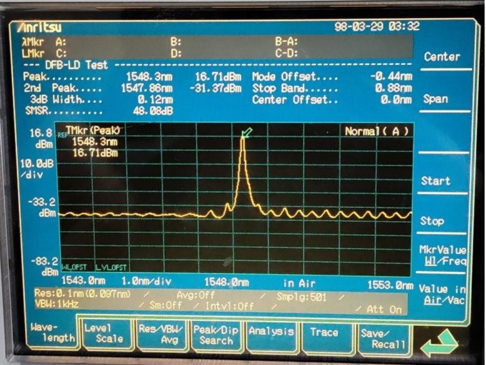
Typical Data
Electrical Schematic
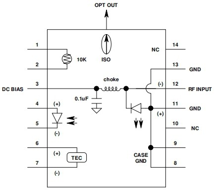
| Lead# | Function | Lead# | Function |
| 1 | Thermistor | 8 | GND |
| 2 | Thermistor | 9 | GND |
| 3 | LD-(Bias) | 10 | NC |
| 4 | PD anode | 11 | GND(LD+) |
| 5 | PD cathode | 12 | RF IN |
| 6 | Cooler+ | 13 | GND(LD+) |
| 7 | Cooler- | 14 | NC |
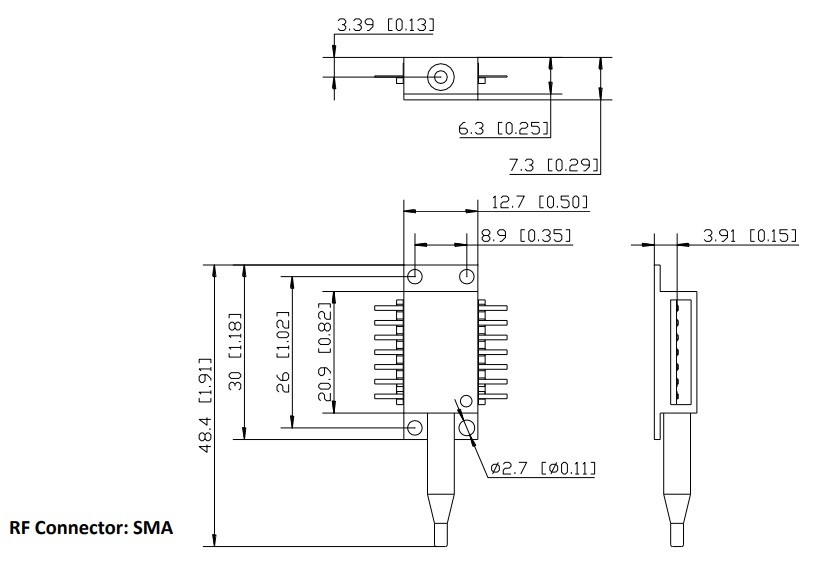
Dimension and Pins ( Unit: mm[inch] )
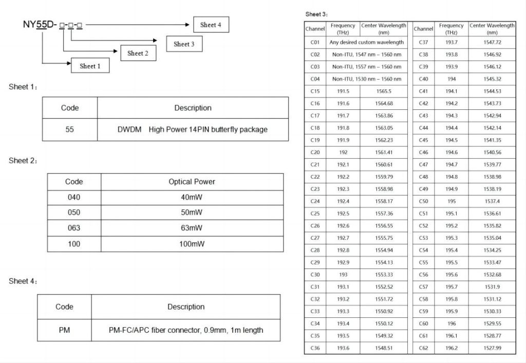
Ordering Information
Precautions
- The fiber bending radius is no less than 20 mm to avoid fiber damage.
- Be sure the fiber coupling facet is clean before connecting it to the Opto-circuit.
- Suitable ESD protection is required in storage, transportation, and use.
We are happy to provide you with commercial services. If you have any questions or needs about our laser diode module, please feel free to contact us.


