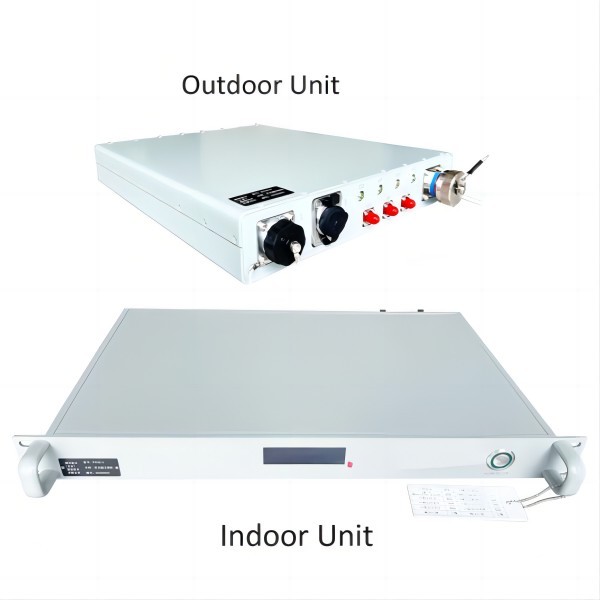
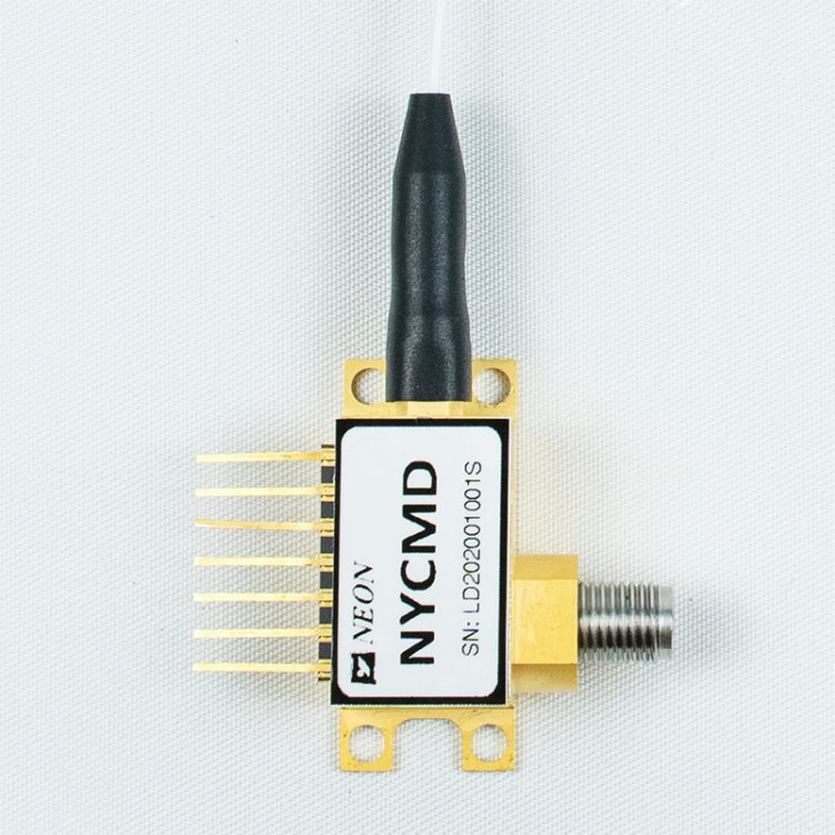
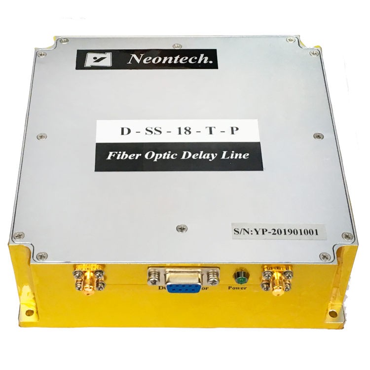
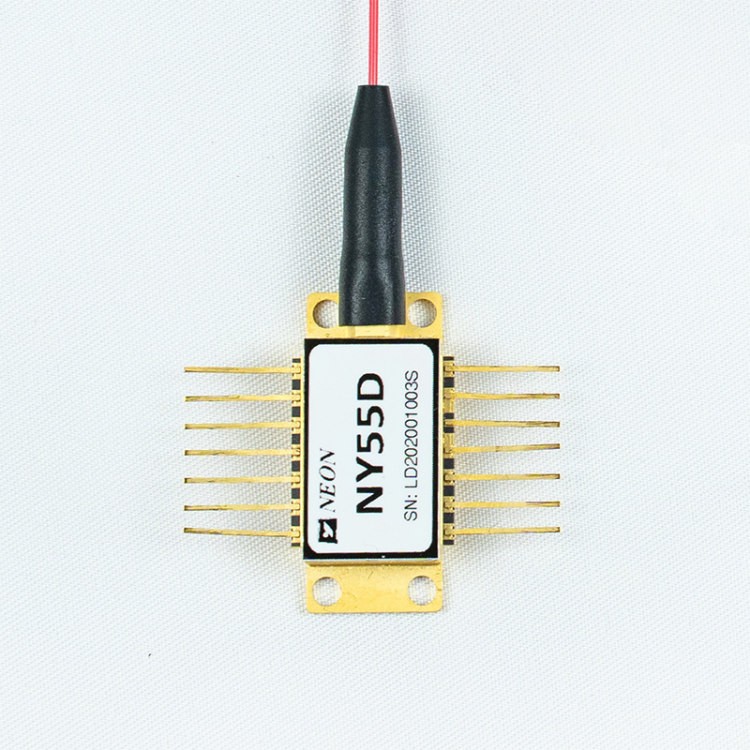
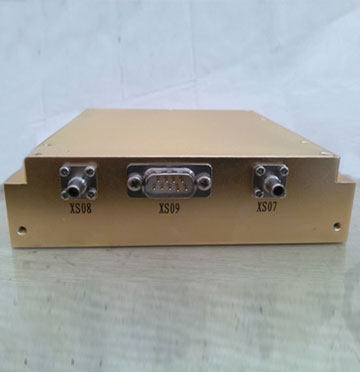
NY048 Series Multifunctional Optical Transceiver
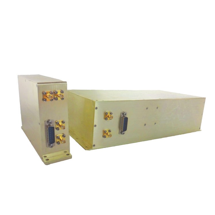
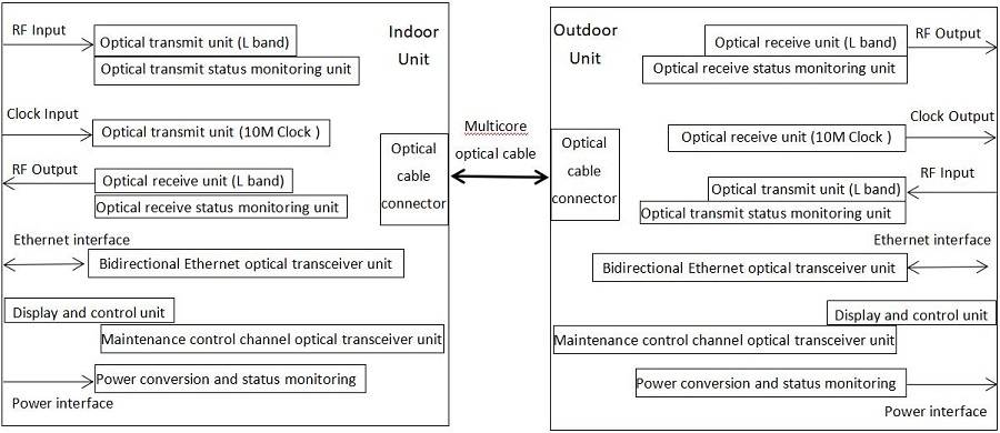
- Fiber and cable are used as carriers to achieve RF signal transmission, status signal and control signal transmission, Ethernet communication, etc. between the central computer room and outdoor radar terminal equipment in the satellite system.
- Consists of an indoor unit and an outdoor unit, completing the uplink and downlink full duplex transmission of L-band RF signals. The uplink is for controllable transmission of a 10 MHz clock signal, which can realize the real-time display of work status and recording and reporting of fault status. The downlink is used as an adaptive bidirectional Ethernet communication interface of 100M/1000M.
- NY048 Series adopts a modular design. Each functional module adopts independent chambers to reduce interference between modules. The overall closed design of metal materials effectively prevents external signal interference and insulates signal leakage from interfering with other devices.
- Waterproof functions on the installation surface.
Feature
- Transmitting Analogue and Digital Signal
- WDM (Wavelength Division Multiplexing)
- High Reliabilit
- Strong Anti-interference Ability
Application
- Ground receive station of satellite system
- Radar system
- Mobile communication terminal
NY048 Series Multifunctional Optical Transceiver uses optical cables as the long-distance transmission medium for signals. Compared to traditional cable transmission, optical cable transmission has advantages such as wider bandwidth, stronger anti-interference, better confidentiality, lower system power consumption, and lighter weight. Not only can it be used for communication between radars and base stations in traditional radar ground stations, but also for communication between radars and signal processing centers in mobile or vehicular stations. After a portable upgrade, it can also be used in mobile radar communication systems.
Schematic
Electrical / Optical Characteristics
| Signal | Parameter | Value | Unit | Remark | ||
| Min | Typ | Max | ||||
| RF Signal | Frequency | 950 | – | 2150 | MHz | – |
| Input signal power range | -60 | – | 0 | dBm | – | |
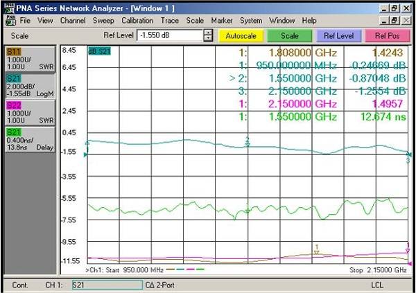
| Link insertion loss | – | – | 1 | dB | Adaptive within 0~5km transmission distance | |
| Gain Flatness | – | – | ±1.5 | dB | – | |
| Group delay distortion | – | – | 0.5 | ns | – | |
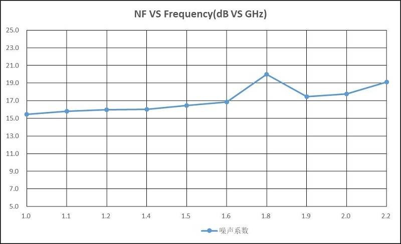
| Noise Figure | – | – | 20 | dB | At room temperature | |
| CNR | 30 | – | – | dB | – | |
| Input 1 dB Compression | 0 | – | – | dBm | – | |
| Spurious suppression ratio | 50 | – | – | dBc | Input power 0dBm | |
| IM3 rejection ratio of output signal | 40 | – | – | dBc | Input power 18dBm | |
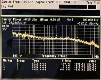
| Phase noise of output signal | – | – | -63 | dBc/Hz | @100Hz | |
| – | – | -73 | dBc/Hz | @1KHz | ||
| – | – | -83 | dBc/Hz | @10KHz | ||
| – | – | 93 | dBc/Hz | @100KHz | ||
| VSWR at input and output ports | – | – | 1.5 | – | 50Ω | |
| Clock Signal | Frequency | 10 | – | – | MHz | – |
| Input power | – | 6 | – | dBm | – | |
| Output power | 5 | – | – | dBm | Adaptive within 0~5km transmission distance | |
| VSWR at input and output ports | – | – | 1.5 | – | 50Ω | |
| Status display and control function | Display and control various working states of indoor and outdoor units | |||||
| Ethernet functionality | Full duplex 100/1000M Ethernet transmission | |||||
Power Supply
|
Item |
Symbol |
Description |
Unit |
Remark |
|
Indoor Unit |
DC |
+12@10W |
V |
220VAC to +12VDC Power supply with power adapter |
|
Outdoor Unit |
DC |
+12@15W |
V |
220VAC to +12VDC Power supply with power adapter |
Display function

|
Symbol |
Description |
Remark |
|
D&T: |
Display date and time |
|
|
≮:Indoor unit status information display |
||
|
ALL: |
Comprehensive status. Including transmission status, reception status, working current status, and optical power receiving status |
■ Any state fault |
|
□ All states are normal |
||
|
Tx |
Transmission status indication of L-band uplink signal |
■ Fault □ Normal |
|
Rx |
Reception status indication of L-band downlink signal |
■ Fault □ Normal |
|
I |
Current status indication |
■ Fault □ Normal |
|
RP |
Optical power receiving of L-band downlink signal(dBm) |
|
|
≯:Outdoor unit status information display |
||
|
ALL |
Comprehensive status. Including transmission status, reception status, working current status, and optical power receiving status |
■ Any state fault |
|
□ All states are normal |
||
|
CLK |
Indication of Clock signal receive output electric power |
■ Fault □ Normal |
|
Tx |
Transmission status indication of L-band uplink signal |
■ Fault □ Normal |
|
Rx |
Reception status indication of L-band downlink signal |
■ Fault □ Normal |
|
I |
Current status indication |
■ Fault □ Normal |
|
RP |
Optical power receiving of L-band downlink signal(dBm) |
|
|
The outdoor unit displays the following statuses with an indicator light |
||
|
X06 |
Optical transmission status of downlink signal |
Green indicator: on means normal,off means fault |
|
X07 |
Optical reception status of uplink signal |
Green indicator: on means normal,off means fault |
|
X08 |
The status of power supply |
Green indicator: on means normal,off means fault |
|
X09 |
Clock signal working state |
Green indicator: on means normal,off means fault or remotely turned off |
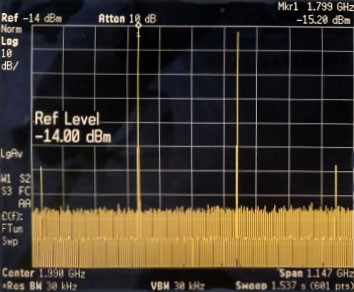
Typical Curve
Dimension and Interface
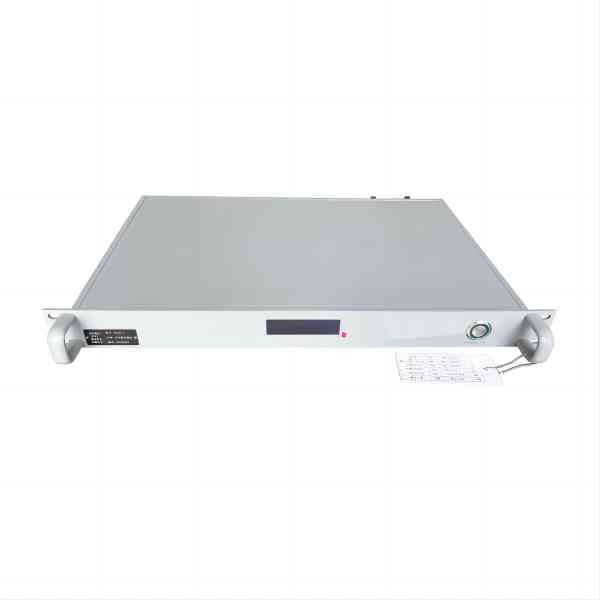
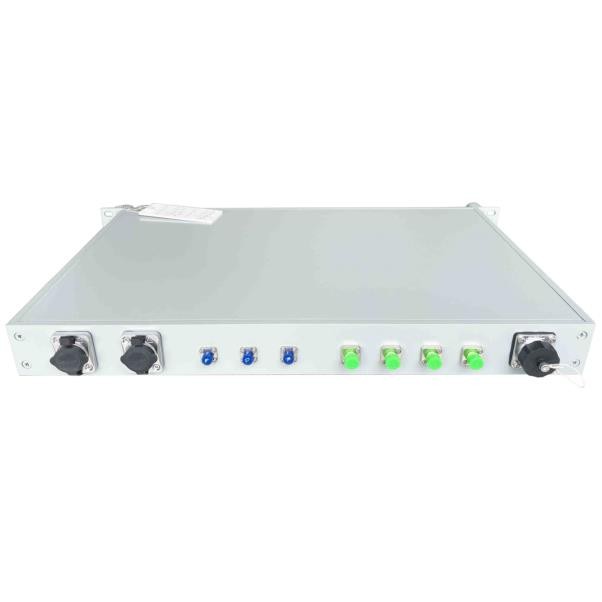
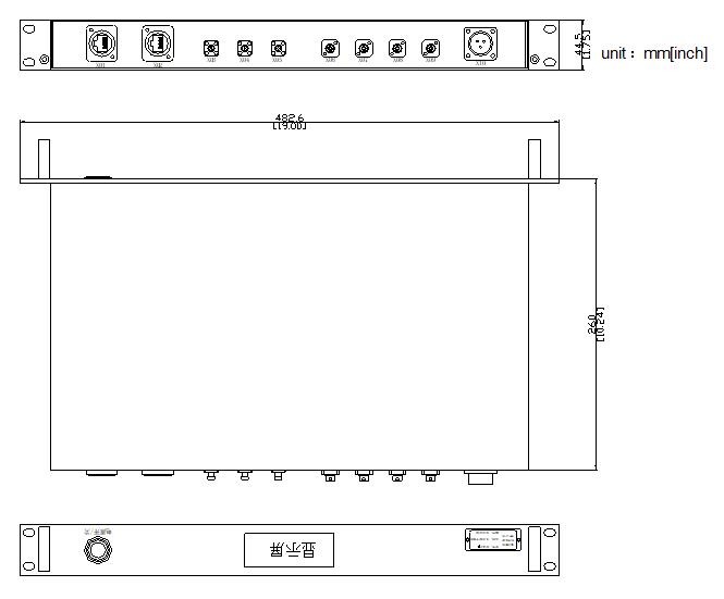
- Indoor Unit: Dimension and Interface
|
Interface Definition of indoor unit |
|||||
|
Symbol |
Description |
Type |
Symbol |
Description |
Type |
|
X01 |
Local Ethernet port |
YT-RJ45 |
X06 |
Optical output of uplink RF signal |
FC/APC |
|
X02 |
Up/down Ethernet port |
YT-RJ45 |
X07 |
Optical input of downlink RF signal |
FC/APC |
|
X03 |
Uplink RF signal input |
SMA-K |
X08 |
Optical output of Clock signal |
FC/APC |
|
X04 |
Downlink RF signal input |
SMA-K |
X09 |
Status information, control signal, optical input, output |
FC/APC |
|
X05 |
Clock signal input |
SMA-K |
X10 |
Power |
WS20-3Z |
|
Power supply:220VAC/50Hz to 12VDC with power adapter |
|||||
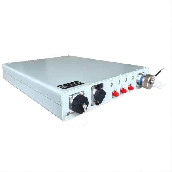
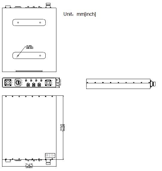
- Outdoor Unit: Dimension and Interface
|
Interface Definition of outdoor unit |
|||||
|
Symbol |
Description |
Type |
Symbol |
Description |
Type |
|
X01 |
Power |
WS20-3Z |
X04 |
Downlink RF signal input |
SMA-K |
|
X02 |
Up/down Ethernet port |
YT-RJ45 |
X05 |
Optical output of Clock signal |
SMA-K |
|
X03 |
Uplink RF signal output |
SMA-K |
X10 |
4-core optical interface |
YMF13F04A1D40N02-S |
|
Power supply:220VAC/50Hz to 12VDC with power adapter |
|||||
|
Outdoor unit: X10(4-core optical interface)Interface Definition |
|||||
|
1(A)core:Uplink signal optical input(Connected to indoor unit X06) |
2(B)core:Downlink signal optical output(Connected to indoor unitX07) |
||||
|
3(C)core:Clock signal optical input(Connected to indoor unitX08) |
4(D)core:State, control composite optical signal(Connected to indoor unitX09) |
||||


