MAMPD-4 Multichannel High-Speed Amplified Microwave Photodetector
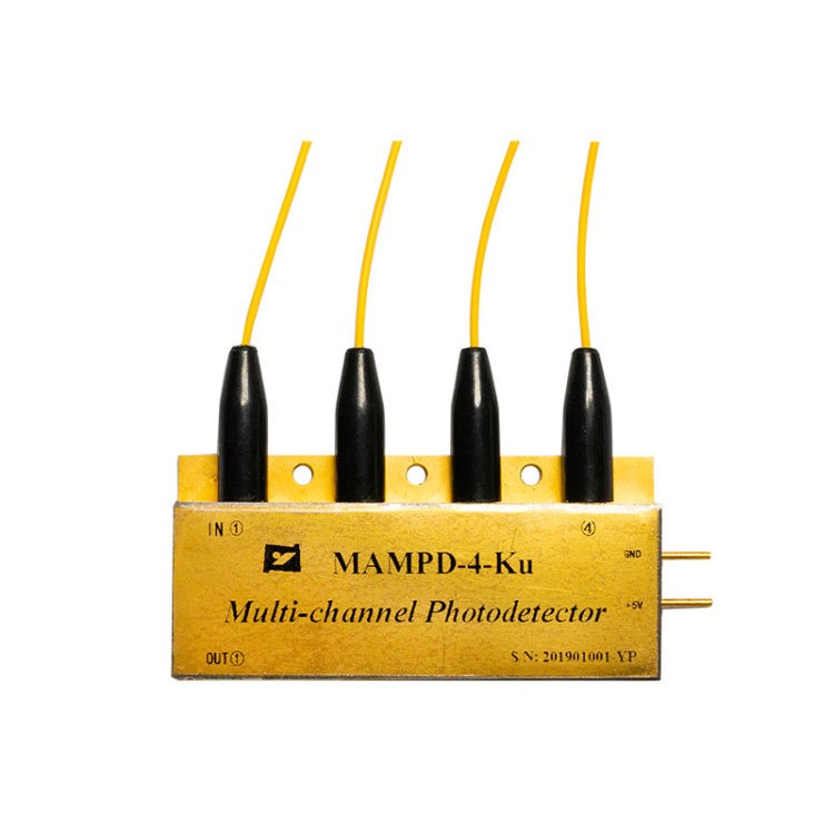
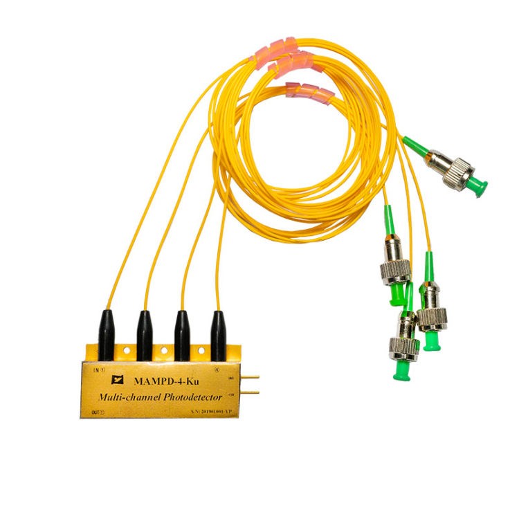
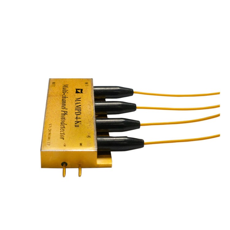
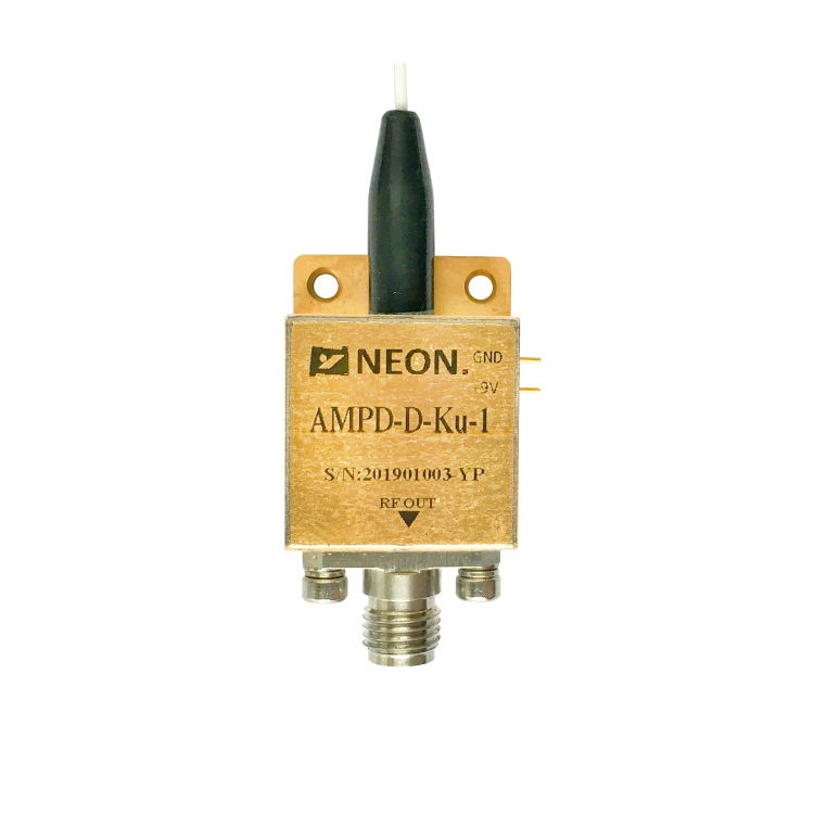
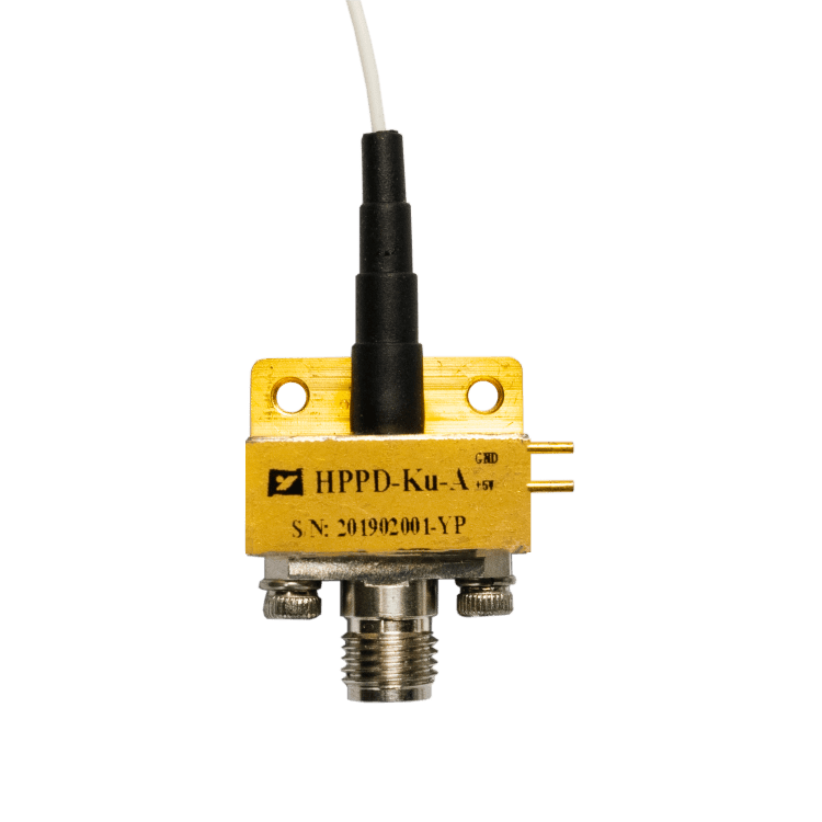
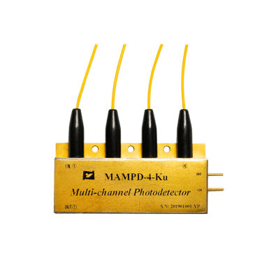
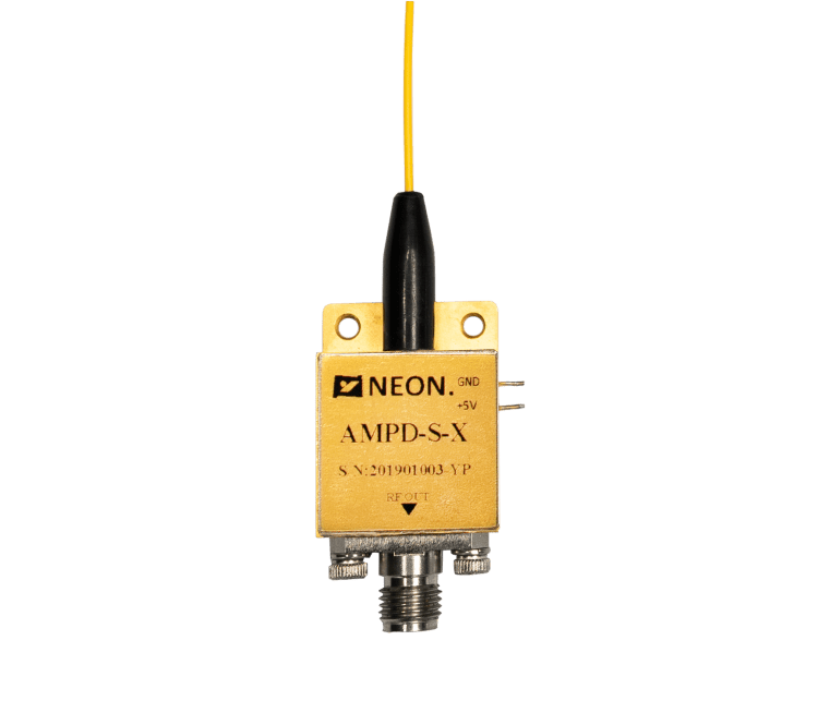
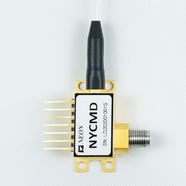
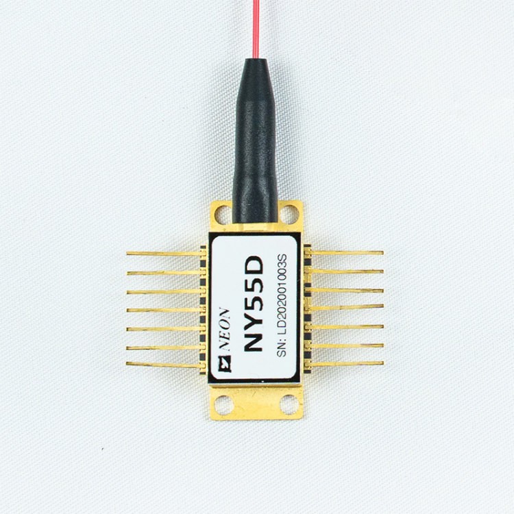
MAMPD-4 is an optoelectronic hybrid integrated by broadband InGaAs photodiode and low noise amplifier. Wavelength:1000 to 1650nm, Gain:15 dB, Bandwidth/Frequency: 12GHz and 18GHz, Optical input: Standard single-mode 9/125μm fiber, RF output: SMP compatible connector, hermetically sealed, Weighs less than 62 grams, ROHS 2.0 certificated.
Introduction of MAMPD-4 Multichannel High-Speed Amplified Microwave Photodetector
The MAMPD-4 is an optoelectronic hybrid integrated by broadband InGaAs photodiode and low noise amplifier. The response wavelength of the InGaAs PIN photodiode is 1000 to 1650nm. The RF gain of a low-noise amplifier is 15 dB.
MAMPD-4 can provide a bandwidth of 12GHz and 18GHz. The module operates on +5V supply voltages. It complies with a standard single-mode 9/125μm fiber input. The RF output port is an SMP-compatible connector matched by 50 ohm impedance.
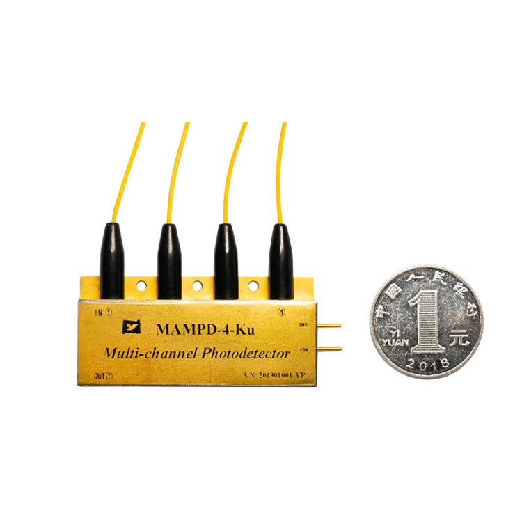
MAMPD-4 is hermetically sealed and weighs less than 62 grams.
ROHS 2.0 certificated.
Features of MAMPD-4 Multichannel High-Speed Amplified Microwave Photodetector
- Wide Bandwidth
- Incorporated Bias-T
- O/E Hybrid Integrated
- High Gain, Low Noise, Broadband
- Hermetically Sealed, SMP connector
Applications of MAMPD-4 Multichannel High-Speed Amplified Microwave Photodetector
- Radar Information Processing
- Electronic Warfare
- Antenna Measurement
MAMPD-4 Multichannel High-Speed Amplified Microwave Photodetector Selection
| Typical & Absolute Maximum Rating | |||||||
| Parameter | Sym. | Typ | Rating | Unit | |||
| Storage temperature range | TSTG | -45 ~ +85 | -55 ~ +100 | ℃ | |||
| Operating case temperature range | TC | 25 | -40 ~ +85 | ℃ | |||
| Bias Voltage | VR | 5 | +5 ~ +9 | V | |||
| Optical Input Power | Pin | 0 | 10 | dBm | |||
| Burn-out Optical Power | PB | – | 13 | dBm | |||
| Lead soldering temperature | Tp | 280(10s) | 330(10s) | ℃ | |||
| Electrical / Optical Characteristics (TC = 22 ± 3 ℃ ) | ||||||||||
| Parameter | Sym | Test Condition | Parameter Values | Unit | ||||||
| Wavelength Range | λ | - | 1000 ~ 1650 | nm | ||||||
| Frequency Range | - | - | X – Band | Ku – Band | - | |||||
| Small Signal Bandwidth | f-3dB | TC = 22 ± 3℃ | 0. 3 ~ 12 | 2 ~ 18 | GHz | |||||
| Responsivity | Re | VR =+5V, Pin =10mW | λ = 1310 nm | ≥ 0.8 | ≥ 0.85 | A/W | ||||
| λ = 1550 nm | ≥ 0.85 | ≥ 0.8 | ||||||||
| Amplitude Flatness | A | TC =-45~+85 ℃ | ≤ ± 2 | dB | ||||||
| Saturation Optical Power | Ps | VR =+ 5 V, λ = 1550 nm | 10 | dBm | ||||||
| AC Modulated | ||||||||||
| RF Signal Gain(Typical) | G | - | 15 ± 1 | dB | ||||||
| Saturation RF Output Power | Pout | - | 3 | dBm | ||||||
| Output VSWR | VSWR | - | ≤ 2 | - | ||||||
| Output Impedance | RL | - | 50 | Ω | ||||||
Typical Response Curves
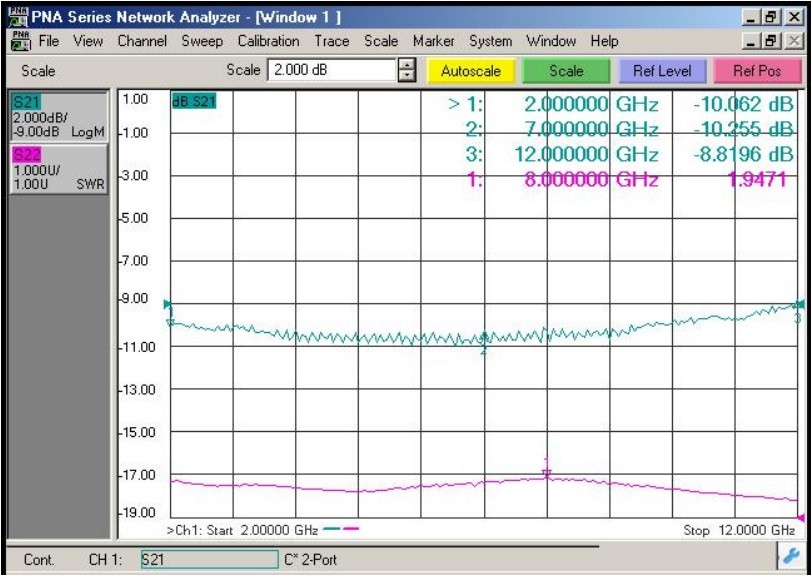
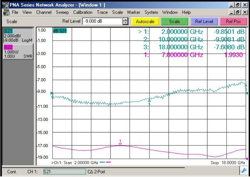
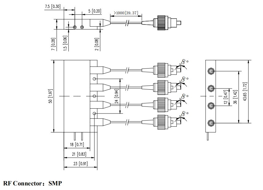
Dimension and Pins ( Unit: mm[inch] )
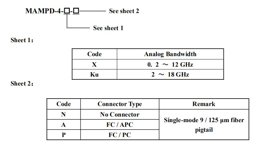
Model Information
Precautions
- The fiber bending radius is no less than 20 mm to avoid fiber damage.
- Be sure the fiber coupling facet is clean before connecting it to the Opto-circuit.
- Suitable ESD protection is required in storage, transportation, and use.
NEON‘s main technology design for:
- Simulate high-speed photoelectric detection
- Digital photoelectric modulation
- High-speed photoelectric transceiver components
- The various fiber-optic transmission facility
We are happy to provide you with commercial services. If you have any questions or needs about our high-speed photodetectors, please feel free to contact us.


