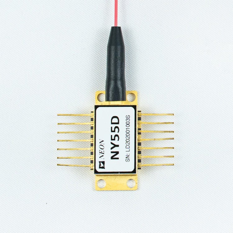
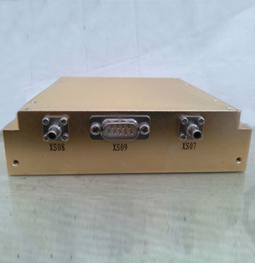
NYDMD Series – DWDM Microwave DFB Laser Module
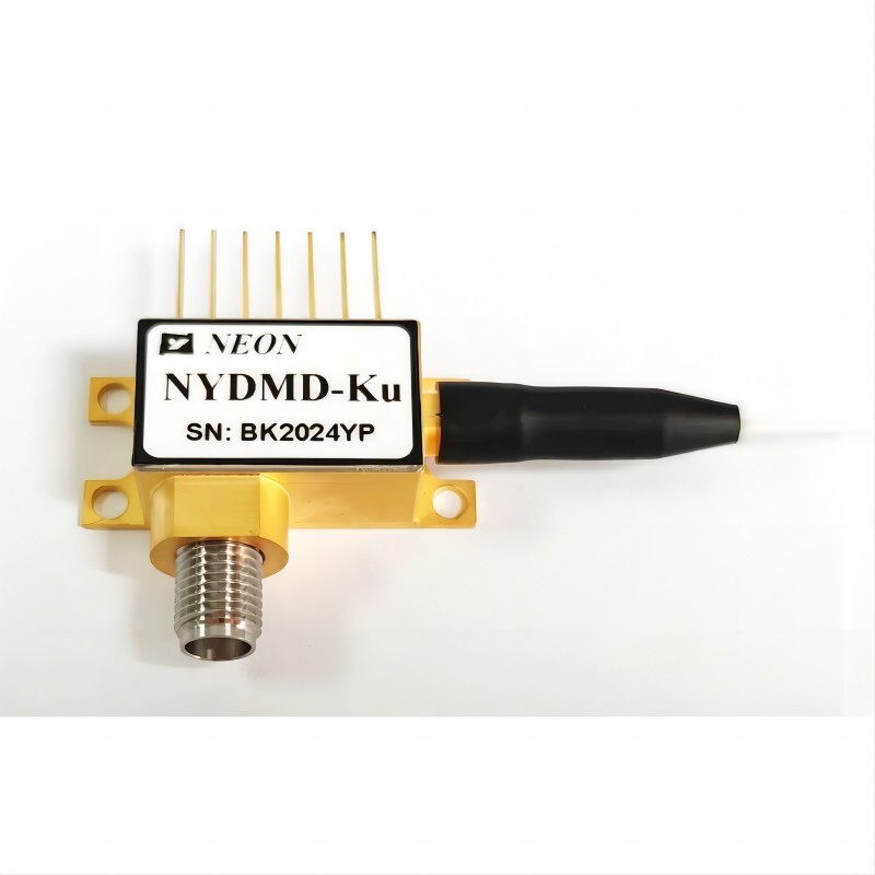
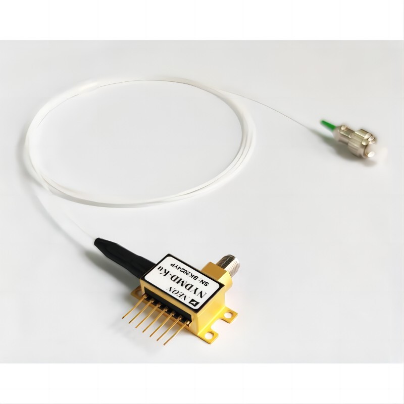
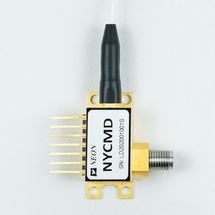
- NYDMD series module is a directly modulated DFB laser that provides exceptional performance for linear fiber optics communications in very wide bandwidth applications.
- NYDMD’s linear fiber optic lasers are an excellent alternative to using coaxial cable systems to transmit 12 GHz or 18 GHz signals.
- They offer significant improvements in the reliability of microwave communications networks by transmitting the RF signal in its original format.
- As a result of these properties, laser products provide significant improvements in signal quality for a wide variety of applications including antenna remoting, telemetry, timing and reference signal distribution, measurement, and delay lines.
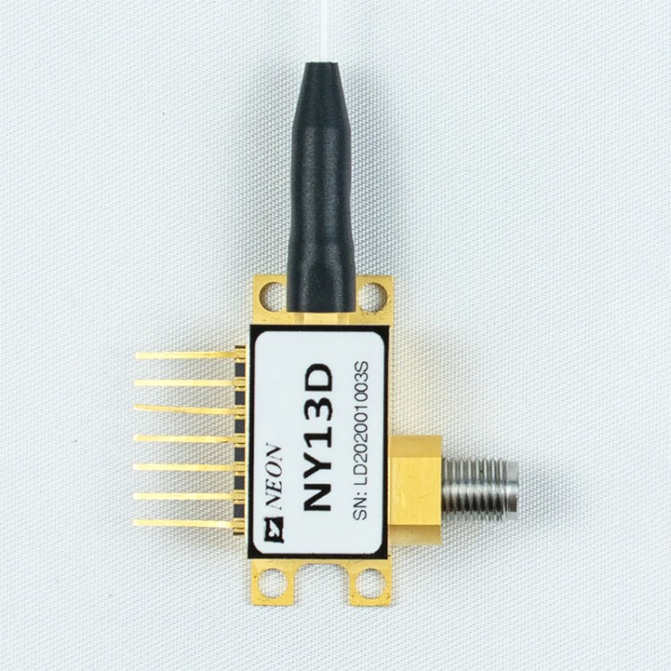
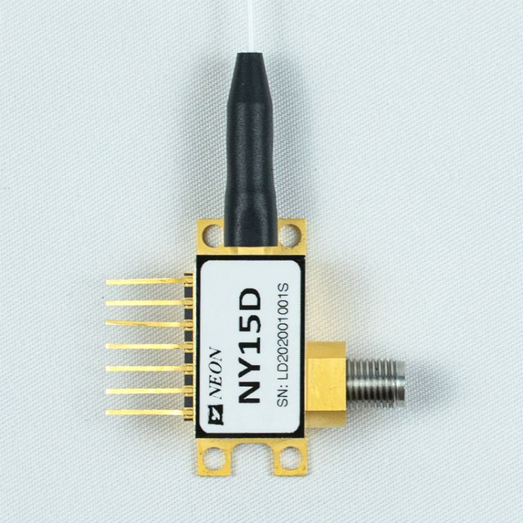
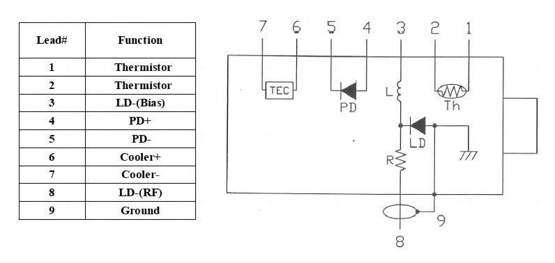
- The NYDMD series laser built-in optical isolator, TEC, thermistor, laser diode chip, and monitor photodiode are hermetically sealed in a 7PIN butterfly package.
Attachment
Features of DWDM Microwave DFB Laser Module
- High-Dynamic-Range
- 18 GHz Bandwidth
- Wavelength: DWDM(ITU)
- Low threshold current
- High output power
- 7pin butterfly package with SMA connector
- Operating case temperature: -40 to 70℃
- High reliability
Applications of DWDM Microwave DFB Laser Module
- Antenna Remoting
- Cellular and PCS Networks
- Analog RF links transmission
- Military Communications
- Tracking, Telemetry, and Control
DWDM Microwave DFB Laser Module Performance Specifications
| Absolute Maximum Ratings | ||||
| Parameter | Symbol | Min. | Max. | Unit |
| Laser diode forward current | If | – | 120 | mA |
| Laser diode reverse voltage | V | – | 1 | V |
| Front power | Pf | – | 20 | dBm |
| PD reverse voltage | V | – | 15 | V |
| Forward current (PD) | Im | – | 2 | mA |
| Operation temperature | To | -40 | 70 | °C |
| Storage temperature | Ts | -55 | 85 | °C |
| Storage relative humdity | Sr | – | 85 | % |
| Optical and Electrical Specification (Tc=25°C) | |||||||
| Parameter | Symbol | Test Condition | Min | Typ | Max | Units | Note |
| Wavelength | λ | IF = IOP, T = TOP | DWDM (ITU) | nm | |||
| 1550 | |||||||
| – | |||||||
| Frequency | – | X Option | 0.1 | – | 12 | GHz | – |
| Ku option | 1 | – | 18 | ||||
| Optical Output Power | P | IF=Iop | – | 10 | – | mW | 1 |
| Thershold current | Ith | λ=1550nm | – | – | 10 | mA | – |
| Operation current | Iop | λ=1550nm | – | 55 | 100 | mA | – |
| Operation voltage | Vop | λ=1550nm | – | 1.5 | 2.5 | V | – |
| Slope efficiency | SE | – | 0.2 | – | – | W/A | – |
| Side-mode suppression ratio | SMSR | λ=1550nm ,IF=Iop | 30 | – | – | dB | – |
| Rative Intensity Noise | RIN | – | -150 | -130 | dB/Hz | – | |
| Bandwidth (-3dB,I=60mA) | S21 | X Option | – | 12 | – | GHz | – |
| Ku option | – | 18 | – | ||||
| VSWR | VSWR | X Option | – | – | 2 | – | – |
| Ku option | – | – | 2.2 | ||||
| Input 1 dB Compression | – | 15 | – | – | dBm | – | |
| Thermistor Resistance | Rth | @25°C | – | 10 | – | Kohm | – |
| TEC current | It | – | – | – | 1.2 | A | 2 |
| TEC voltage | Vt | – | – | 2.5 | V | 2 | |
| Capacitance (PD) | Ct | – | – | 20 | pF | – | |
| Monitoring current | Im | – | 0.1 | – | 2 | mA | – |
| Dark current (PD) | Id | – | – | 50 | nA | – | |
| Output Impedance | RL | – | – | 50 | – | Ω | – |
Notes: All laser chips come from wafers that have been certified using a representative lot of devices that must achieve an acceptable yield for burn-in.
- Laser temperature set 25℃, bias current at 55mA
- Operation case temperature -40~70℃
Typical Data
(λ=1550nm , TC =25 ℃)
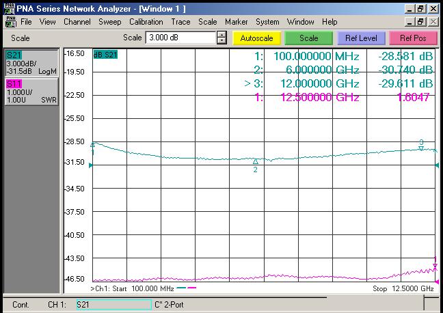
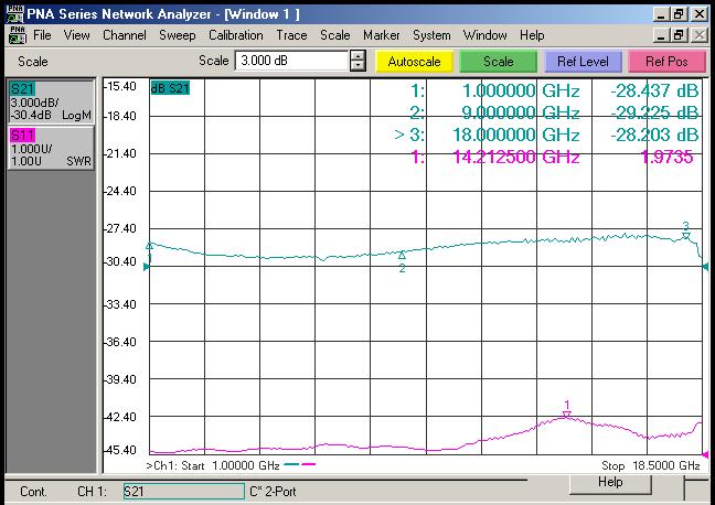
Electrical Schematic
Dimension and Pins ( Unit: mm[inch] )
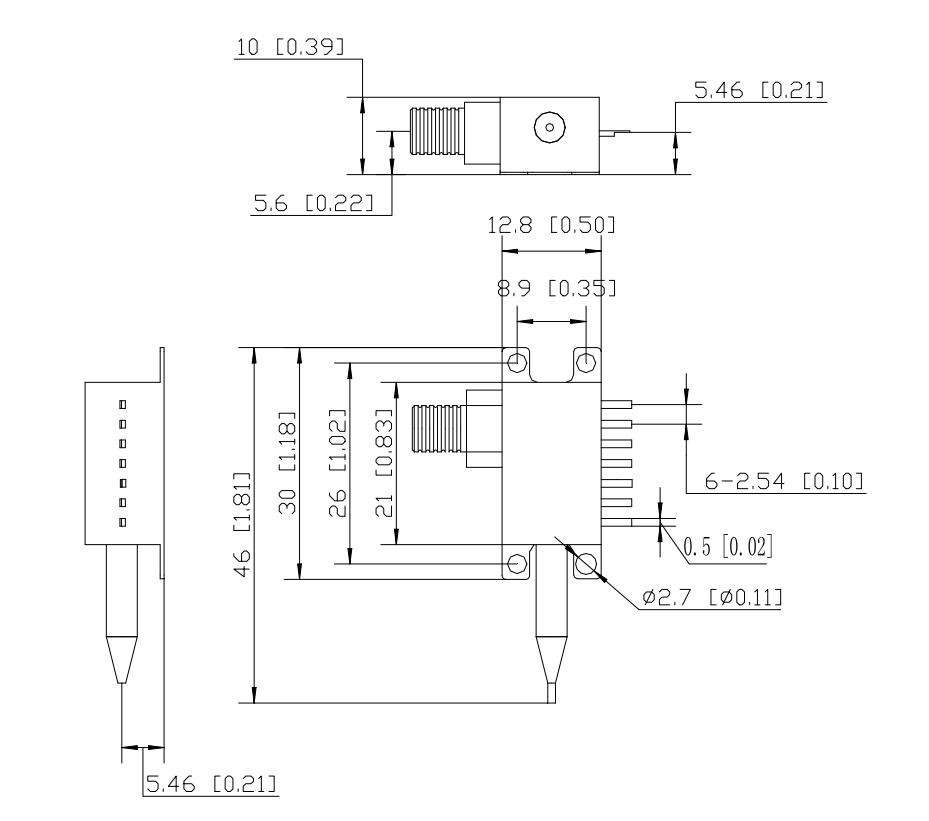
RF Connector: SMA
Ordering Information

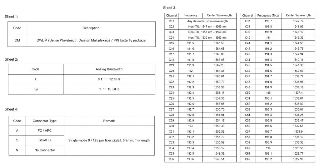
Precautions
- The fiber bending radius is no less than 20 mm to avoid fiber damage.
- Be sure the fiber coupling facet is clean before connecting it to the Opto-circuit.
- Suitable ESD protection is required in storage, transportation, and use.
We are happy to provide you with commercial services. If you have any questions or needs about our laser diode module, please feel free to contact us.


