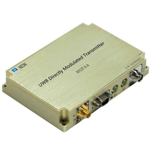
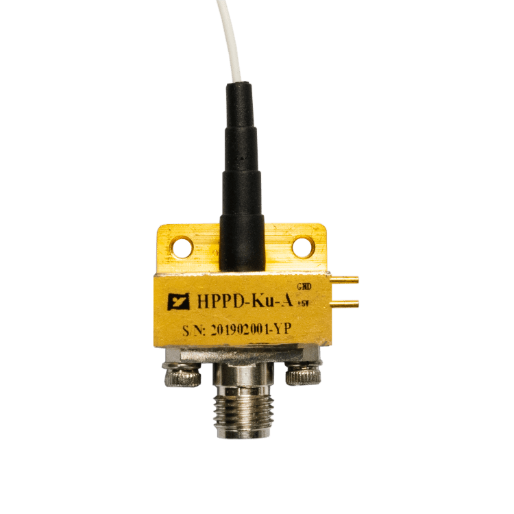
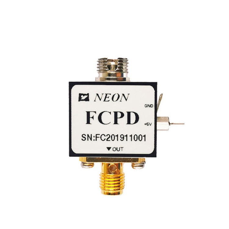
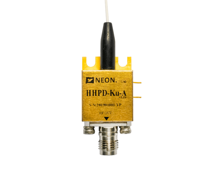
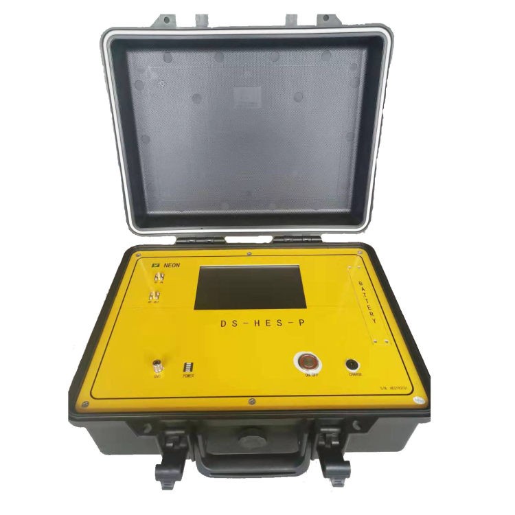
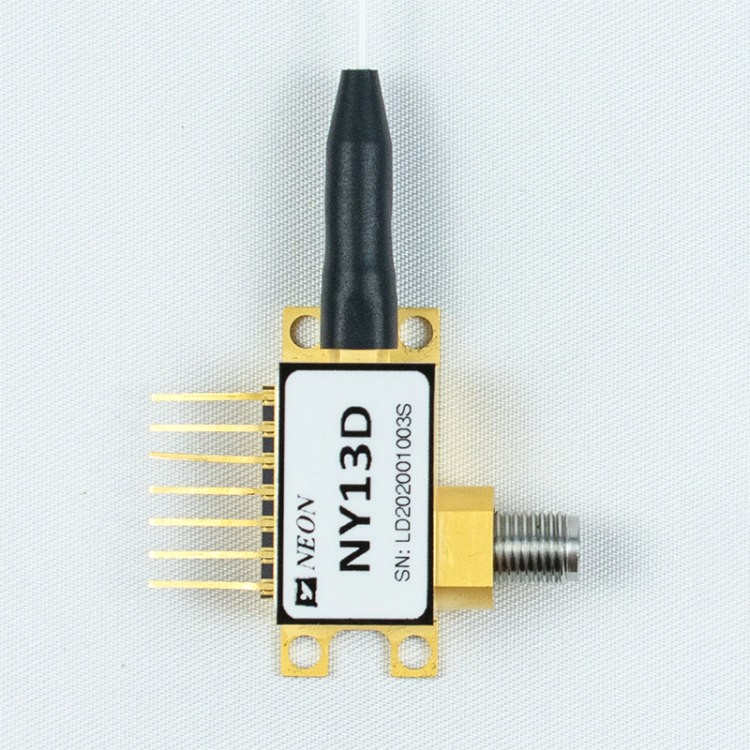
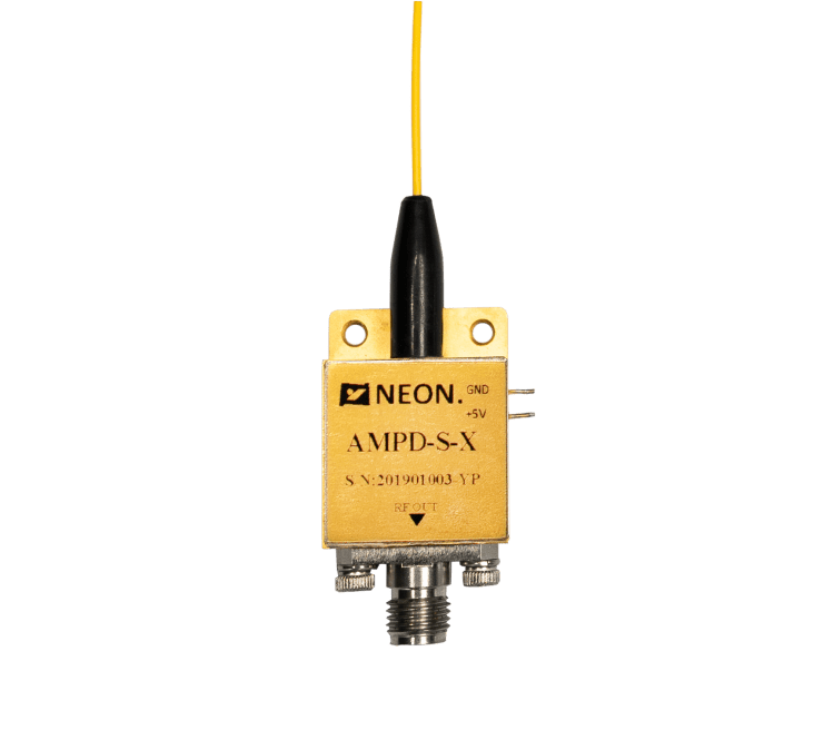
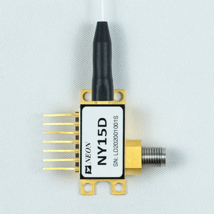
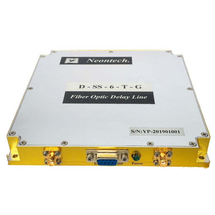
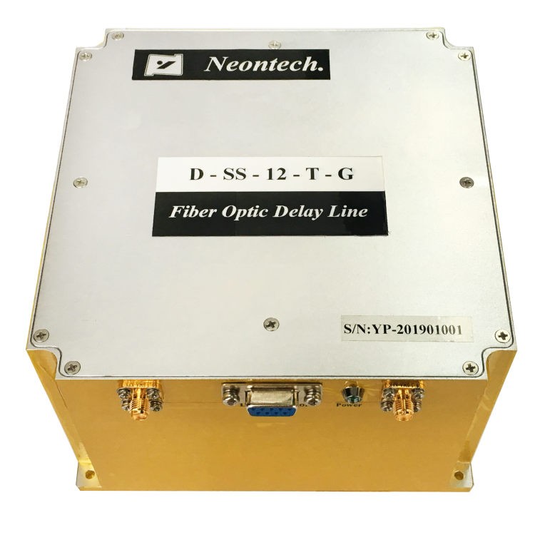
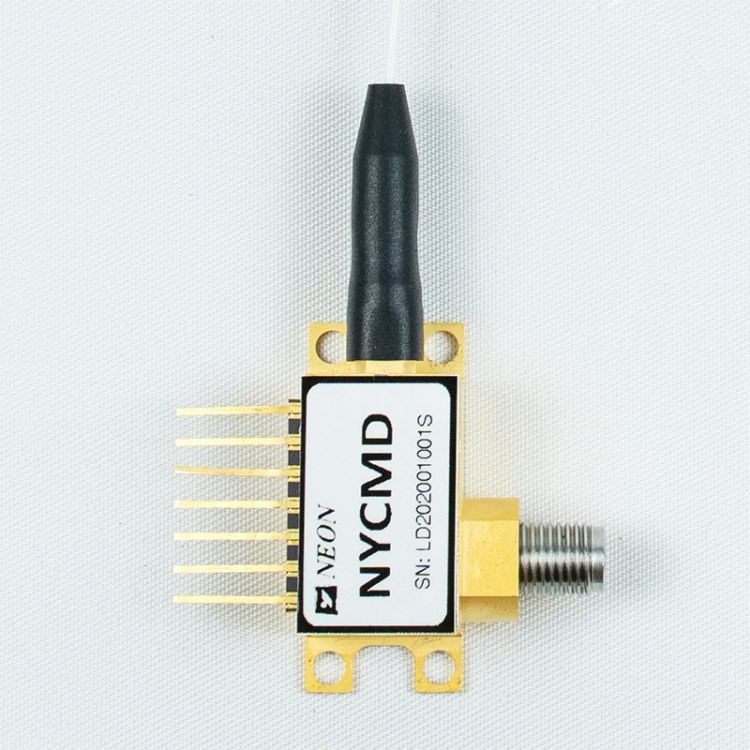
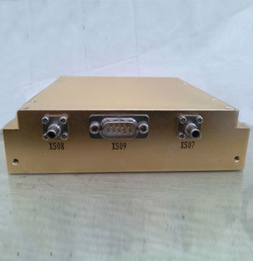
NY13T Series UWB Directly Modulated Transmitter
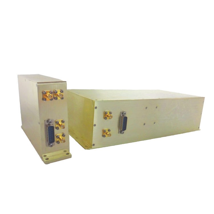
NY13T Transmitters are mainly composed of a high-speed directly modulated DFB laser, an automatic optical power control circuit, an automatic temperature control circuit, a voltage-stabilizing conversion circuit, and a monitoring and indicating circuit.
NY13T Transmitter works at 1310nm. The modulation bandwidth is better than 18GHz. Output power can reach 10mW. Low relative intensity noise. Take good stability of output wavelength. The power supply of the NY13T Transmitter is a single positive power supply, which can work stably in the voltage range of +7V ~+36V.
Besides, the NY13T Transmitter also has the function of indicating that the power supply and optical power output are normal.
Product Features
- Ultra-wideband (better than 18GHz )
- Operating case temperature:(-40℃~70℃)
- High-Dynamic-Range
- High output power
- Low RIN
Application
- Antenna&Radar
- Electronic countermeasure system
- Analog RF links transmission
- Broadband Wireless Communication
- Mobile communication base station
Absolute Maximum Ratings
| Parameter | Symbol | Min. | Typ. | Max. | Unit |
| Storage temperature | TSTG | -55 | +25 | +85 | ℃ |
| Operation temperature | TC | -40 | +25 | +70 | ℃ |
| RF input power1 | Pin | – | +10 | +20 | dBm |
| Voltage | Vin | +7 | +12 | +36 | V |
(1) Continuous wave (CW) working mode.
Optical and Electrical Specification (TC = 22±3℃)
| Parameter | Symbol | Condition | Min. | Typ. | Max. | Unit |
| Wavelength | λ | – | – | 1310 | – | nm |
| Frequency(3dB) | f3dB | X band | 0.1 | – | 12 | GHz |
| Ku band | 1 | – | 18 | |||
| Light output power | P | – | 5 | 10 | – | mW |
| Relative Intensity Noise | RIN | – | – | – | -155 | dBc/Hz |
| Return loss(VSWR) | VSWR | X band | – | – | 2 | – |
| Ku band | – | – | 2.2 | |||
| Input 1 dB Compression | – | – | +13 | +15 | – | dBm |
Power Supply (TC = 22±3℃)
|
Parameter |
Min. |
Typ. |
Max. |
Unit |
|
Voltage |
+7 |
+12 |
+36 |
V |
|
Current(2) |
0.07 |
0.1 |
1 |
A |
(1) Test condition: Vin=+12V.
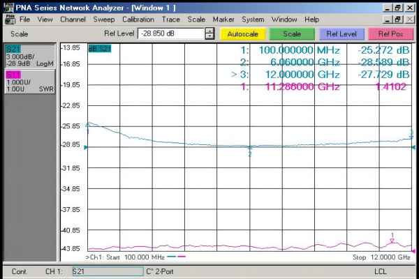
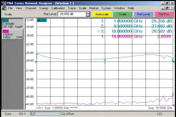
Typical Response Curve
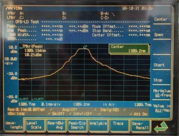
Typical Spectrogram
Dimension Unit: mm[inch]
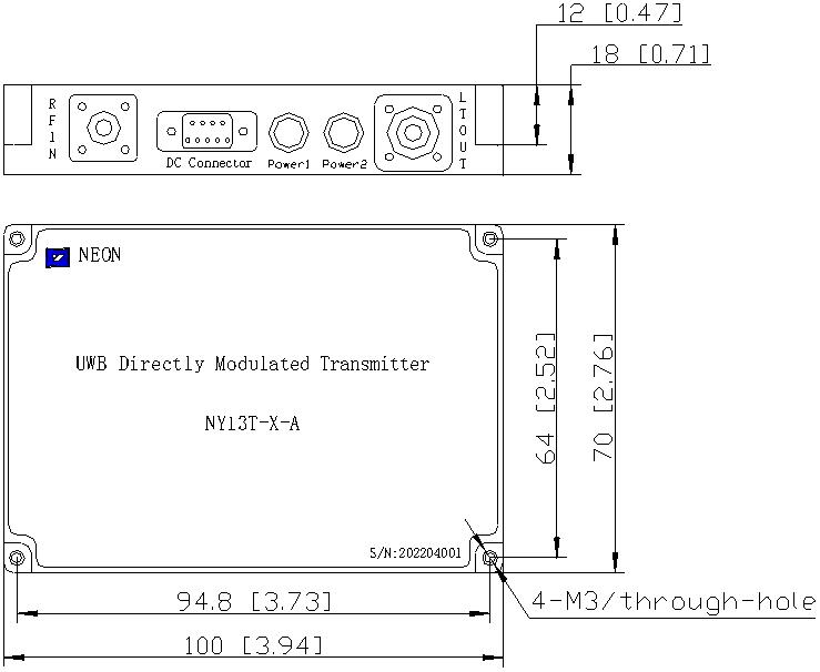
RF Connector: SMA
Power Connector: J30J-9-ZKP
Pin Of Power Supply
|
Parameter |
Description |
||||||||
|
Pin |
1 |
2 |
3 |
4 |
5 |
6 |
7 |
8 |
9 |
|
Voltage |
Vin |
NC |
GND |
NC |
|||||
Order Information


