
What Is Photodetector Noise? Shot Noise, Thermal Noise, Dark Current and TIA Noise Explained
Photodetector noise is one of the most important factors determining the real-world performance of an optical detection system. A photodetector may offer high responsivity, wide bandwidth, and excellent linearity, yet still fail to detect weak optical signals if its noise floor is too high.
Photodetector noise does not come from a single source. It can originate from the statistical nature of photon-to-electron conversion, semiconductor leakage current, thermal effects in electrical components, and the transimpedance amplifier (TIA) used to convert detector current into a usable voltage signal. In high-speed and RF photonics systems, the interaction between these noise sources, bandwidth, optical power, and circuit design becomes particularly important.
Understanding these mechanisms helps engineers select photodetectors more effectively, evaluate datasheet specifications, and determine whether a system is limited by the detector itself or by its associated electronics.
What Is Photodetector Noise?
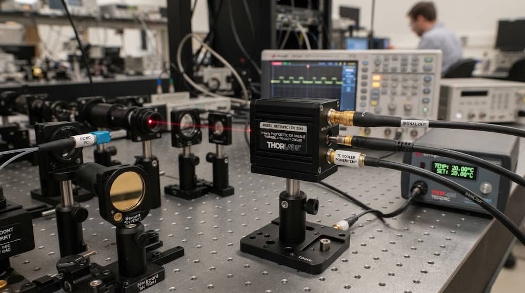
A photodetector converts incident optical power into an electrical signal. Ideally, a stable optical input would produce a perfectly stable electrical output. In practice, the output always contains some random fluctuation around the desired signal. This unwanted fluctuation is referred to as photodetector noise.
A simplified detection chain can be represented as:
Optical Signal → Photodetector → Photocurrent → TIA/Amplifier → Electrical Output
At every stage, additional noise can be introduced. Some noise is fundamentally associated with the detector’s semiconductor physics, while other noise originates from resistors, amplifiers, bias circuits, cables, and measurement equipment.
Photodetector noise matters because it determines how clearly a useful signal can be distinguished from the background. A lower noise floor generally enables better signal-to-noise ratio (SNR), lower detectable optical power, and more accurate optical measurements. The main noise sources encountered in photodetection systems include:
| Noise Source | Primary Origin | Important Parameters |
| Shot noise | Random carrier generation and collection | Photocurrent, dark current, bandwidth |
| Thermal noise | Thermal motion of charge carriers | Temperature, resistance, bandwidth |
| Dark-current noise | Leakage current in the detector | Material, temperature, bias voltage |
| TIA noise | Amplifier and feedback circuitry | Gain, bandwidth, input capacitance |
| Laser RIN | Optical source intensity fluctuations | Laser characteristics, modulation conditions |
The relative importance of each source depends on operating conditions. A detector operating with very weak optical power may be dominated by electronic and dark-current-related noise, while a detector receiving much higher optical power may become increasingly influenced by shot noise.
Shot Noise in Photodetectors
What Causes Shot Noise?
Shot noise is a fundamental noise mechanism caused by the statistical nature of charge carriers. Even when the average optical power is constant, photons do not arrive at the detector at perfectly regular intervals. The resulting generation and collection of electrons therefore exhibit statistical fluctuations. This produces a random variation in photocurrent known as shot noise.
Shot noise is particularly important because it cannot simply be eliminated through better PCB layout or shielding. It is fundamentally associated with the discrete nature of electrical charge and optical detection. For a photodetector with an average current I, the RMS shot-noise current can be approximated by:
ishot=√2qIB
where:
- ishot is RMS shot-noise current
- q is the elementary charge
- I is average detector current
- B is measurement bandwidth
The equation reveals two important relationships. First, shot noise increases with photocurrent. Second, the total integrated shot noise increases with the square root of bandwidth.
However, higher photocurrent also normally means a stronger useful signal. Therefore, increasing optical power does not automatically result in poorer system performance. The important factor is how the signal increases relative to the resulting noise.
When Does Shot Noise Become Dominant?
Shot noise becomes increasingly important when the detector operates with relatively high photocurrent. It can become a primary noise limitation in systems with:
- High optical input power
- High detector responsivity
- Wide electrical bandwidth
- Low electronic noise
- High-speed optical communication signals
This creates an important distinction between electronics-limited and shot-noise-limited detection. At very low optical power, the detector may be limited mainly by TIA and other electronic noise. As optical power increases, shot noise grows and can eventually become the dominant noise source.
Thermal Noise: Johnson-Nyquist Noise Explained
Thermal noise, also called Johnson-Nyquist noise, is generated by the random thermal motion of charge carriers in resistive components. Unlike shot noise, thermal noise is primarily associated with electrical resistance rather than photon-to-electron conversion.
In a photodetection circuit, relevant sources can include:
- TIA feedback resistors
- Load resistors
- Bias circuitry
- Other resistive components in the signal path
The RMS thermal-noise voltage across a resistor can be expressed as:
vn=√4kTRB
where:
- vn is RMS thermal-noise voltage
- k is the Boltzmann constant
- T is absolute temperature
- R is resistance
- B is bandwidth
This relationship highlights two practical factors.
- Temperature: Higher temperature increases thermal noise. This is one reason thermal management can become important in precision optical receivers and other low-noise systems.
- Bandwidth: A wider measurement bandwidth includes more noise power. Therefore, increasing detector bandwidth can improve high-frequency signal detection while simultaneously increasing integrated noise.
This is one of the fundamental trade-offs in high-speed photodetector design:
Higher bandwidth does not automatically mean better overall detection performance. The bandwidth must match the actual signal requirements.
Dark Current and Dark-Current Noise
What Is Photodetector Dark Current?
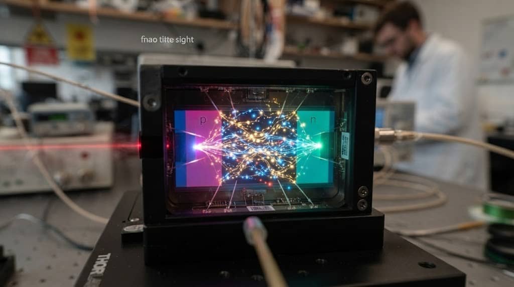
Dark current is the electrical current that flows through a photodetector even when there is little or no incident optical signal. In a reverse-biased photodiode, dark current can originate from semiconductor leakage mechanisms, junction characteristics, defects, surface effects, and thermally generated carriers.
Dark current is normally specified in the photodetector datasheet because it affects both electrical offset and low-light detection performance. For example, a detector designed for weak optical signals generally benefits from low dark current because the useful photocurrent may be relatively small.
How Does Dark Current Generate Noise?
Dark current is not merely a DC offset. Because charge carriers associated with leakage current are also subject to statistical fluctuations, dark current contributes to shot-noise behavior. The corresponding contribution can be considered through the total current flowing through the detector:
Itotal=Iphoto+Idark
Therefore, even when optical input power is extremely low, dark current can contribute to the detector’s noise floor.
This is especially important when:
- Optical signals are weak
- The detector operates at longer wavelengths
- High gain is required
- The measurement bandwidth is large
- The detector operates at elevated temperature
For low-light applications, a photodetector with excellent responsivity but excessive dark current may not provide the expected system-level sensitivity.
Why Temperature Matters
Temperature can significantly affect semiconductor leakage current. As operating temperature increases, dark current may increase, which can increase the associated noise contribution. For demanding applications, therefore, engineers should evaluate dark current together with the intended operating temperature rather than considering the room-temperature specification in isolation.
The practical relationship is:
Higher Temperature → Higher Dark Current → Greater Noise Contribution → Potentially Lower Detection Performance
This is particularly relevant for InGaAs photodetectors operating in the near-infrared and telecommunications wavelength ranges.
TIA Noise: The Often-Overlooked Noise Source
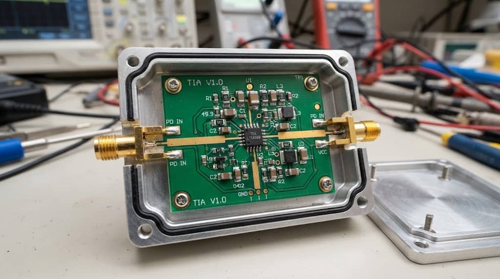
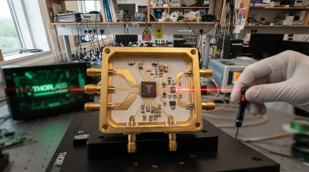
A photodiode generates a current, but many measurement and receiver systems require a voltage output. A transimpedance amplifier (TIA) performs this current-to-voltage conversion. The TIA is therefore an integral part of many high-speed photodetection systems.
A simplified signal path is:
Optical Power → Photocurrent → TIA → Output Voltage
The TIA provides gain and can be designed for high bandwidth, but it also introduces its own noise.
Where Does TIA Noise Come From?
Important contributors include:
- Amplifier input-referred voltage noise
- Amplifier input-referred current noise
- Feedback resistor thermal noise
- Semiconductor device noise
- Parasitic capacitance
- Bias and power-supply noise
The challenge is that TIA gain and bandwidth are closely interconnected. A higher transimpedance gain can improve the output voltage generated from a small photocurrent, but excessive gain can restrict bandwidth or create stability problems. Conversely, designing for very high bandwidth can increase the difficulty of maintaining a low noise floor.
Why TIA Noise Matters in High-Speed Photodetectors
A detector with low intrinsic noise does not necessarily produce a low-noise receiver. If the TIA contributes significant input-referred noise, the electronics may dominate the overall system noise even when the photodiode itself performs well. This distinction is important when comparing packaged photodetectors.
Engineers should determine whether the quoted noise specification applies to:
- The bare photodiode
- The detector module
- The integrated receiver
- A specific TIA configuration
- A specified bandwidth
Comparing noise values without checking these conditions can lead to misleading conclusions.
Shot Noise vs. Thermal Noise vs. Dark Current Noise vs. TIA Noise
The major noise mechanisms have different physical origins and require different mitigation strategies.
| Noise Type | Physical Origin | Main Dependencies | Typical Mitigation |
| Shot noise | Statistical carrier fluctuations | Photocurrent, dark current, bandwidth | Optimize operating current and detector architecture |
| Thermal noise | Thermal charge movement | Temperature, resistance, bandwidth | Thermal management and circuit optimization |
| Dark-current noise | Leakage-current fluctuations | Material, temperature, reverse bias | Low-dark-current detector and proper operating conditions |
| TIA noise | Amplifier/electronic circuitry | Gain, bandwidth, capacitance, circuit design | Low-noise TIA and optimized feedback network |
No single parameter determines the total noise of a photodetection system. A useful engineering approach is to identify which noise source dominates under the intended operating conditions before attempting to optimize the system.
How Photodetector Noise Affects SNR
What Is Signal-to-Noise Ratio?
Signal-to-noise ratio describes the strength of the desired signal relative to the unwanted noise.
In simplified form:
SNR=Psignal/Pnoise
or, when expressed in decibels:
SNRdB=10log 10(Psignal/Pnoise)
For voltage or current quantities under the same impedance conditions, the equivalent RMS ratio can also be expressed using 20 log10. A high SNR means the desired optical signal can be distinguished more clearly from the background noise.
Why More Optical Power Does Not Solve Every Noise Problem
Increasing optical power increases photocurrent and therefore generally strengthens the useful electrical signal. However, it also increases shot noise.
At very low optical power, electronic noise may dominate:
Weak optical signal → Low photocurrent → TIA/electronic noise becomes significant
At higher optical power:
Higher photocurrent → Higher signal + Higher shot noise
The system therefore has different noise regimes depending on optical input power. This is why simply selecting a photodetector with the highest responsivity is not always the best solution. Responsivity must be evaluated together with noise, bandwidth, saturation power, and the expected optical input range.
How Photodetector Noise Affects NEP
Another important parameter closely related to noise is Noise Equivalent Power (NEP). NEP represents the amount of incident optical power required to produce an output signal equivalent to the detector’s noise level under a defined bandwidth condition.
In simplified terms:
Lower NEP → Better ability to detect weak optical signals
Noise and NEP are therefore directly related. A higher noise floor generally results in a higher NEP, while a lower noise floor can enable detection of weaker optical signals.
However, NEP should not be compared without considering the measurement conditions. Bandwidth, wavelength, detector configuration, and whether the specification is normalized to a particular bandwidth can all affect the interpretation. This distinction is important because noise density and total integrated noise are not the same thing.
A detector can have a specified noise density, such as current noise per square root of hertz, while the total noise observed by the system depends on the measurement bandwidth.
How Bandwidth Changes Photodetector Noise
Bandwidth is another critical factor connecting noise and high-speed photodetector performance. For many noise mechanisms, the total integrated noise increases as the measurement bandwidth increases.
Conceptually:
- Narrower Bandwidth → Less Integrated Noise
- Wider Bandwidth → More Integrated Noise
This does not mean that low-bandwidth detectors are inherently better. A 1 GHz detector cannot replace a 30 GHz detector when the application requires a 30 GHz electrical response. Instead, bandwidth should be selected according to the signal requirements.
For example, if an application only contains information within a limited frequency range, unnecessarily increasing the receiver bandwidth can introduce additional noise without providing useful signal information. This creates an important engineering trade-off:
Bandwidth ↔ Noise ↔ Signal Integrity
For high-speed photodetectors, the goal is not simply to maximize bandwidth. The goal is to achieve sufficient bandwidth while maintaining acceptable noise, linearity, saturation power, and overall system performance.
How to Reduce Photodetector Noise
Noise reduction should begin by identifying the dominant noise source. Different mechanisms require different solutions.
Reduce the Impact of Shot Noise
Shot noise is fundamentally related to carrier statistics, so it cannot simply be eliminated. Instead, engineers can optimize the operating point by considering:
- Optical input power
- Detector responsivity
- Required signal level
- Operating bandwidth
- Detector architecture
The objective is to achieve sufficient signal strength without unnecessarily pushing the detector toward saturation or excessive photocurrent.
Reduce Thermal Noise
Thermal noise can be managed through:
- Appropriate resistance selection
- Circuit optimization
- Temperature control
- Reduction of unnecessary bandwidth
- Proper component selection
Thermal design becomes particularly important in high-gain receivers and precision measurement systems.
Reduce Dark-Current Noise
Possible approaches include:
- Selecting a photodetector with low dark current
- Controlling operating temperature
- Selecting an appropriate reverse-bias condition
- Choosing a semiconductor material suited to the wavelength and application
For weak-signal applications, dark current should be treated as a key selection parameter rather than an afterthought.
Reduce TIA Noise
TIA optimization can involve:
- Low-noise amplifier selection
- Appropriate transimpedance gain
- Feedback resistor optimization
- Input capacitance reduction
- Bandwidth optimization
- Careful PCB and RF layout
- Clean power and bias supply design
The detector and TIA should be treated as a combined system. Optimizing only one component may not produce a meaningful improvement in overall receiver noise.

How to Choose a Low-Noise Photodetector
When selecting a photodetector, engineers should avoid focusing on one specification such as responsivity or noise alone. A practical selection process is:
1. Define the operating wavelength: Determine whether the system operates around 850 nm, 1310 nm, 1550 nm, or another wavelength range.
2. Define the optical input range: Determine both the minimum detectable signal and maximum expected optical power.
3. Define required bandwidth: Select sufficient bandwidth for the actual signal rather than automatically choosing the highest available value.
4. Evaluate noise: Review noise density, NEP, dark current, and relevant receiver noise specifications.
5. Check responsivity: Ensure that the detector produces sufficient photocurrent at the intended wavelength.
6. Check saturation power: The detector must accommodate the maximum expected optical input without significant compression.
7. Evaluate linearity and dynamic range: This becomes particularly important in RF photonics, microwave photonics, radar, and other analog optical links.
8. Evaluate the electrical interface: For high-speed applications, RF connector type, impedance, coupling configuration, and output characteristics can affect the complete signal path.
The best detector is therefore not necessarily the one with the lowest published noise value. It is the detector whose noise, bandwidth, responsivity, optical power range, linearity, and electrical interface match the application requirements.
Practical Example: Diagnosing an Unexpectedly High Noise Floor
Consider an InGaAs photodetector operating around 1550 nm. The system is designed to detect a relatively weak optical signal, but the measured RF output contains significantly more noise than expected. A systematic troubleshooting process is more effective than immediately replacing the detector.
Step 1: Check the Optical Input
Verify that the optical source is stable and that the actual optical power reaching the detector is within the intended operating range. Laser intensity noise can sometimes be mistaken for detector noise.
Step 2: Check Dark Current
Block the optical input and measure the detector’s electrical output. An unexpectedly high dark current may indicate an operating-condition or detector issue.
Step 3: Check Reverse Bias
Verify that the detector is operating at the specified bias voltage. Bias conditions can affect capacitance, bandwidth, dark current, and overall detector performance.
Step 4: Check Temperature
Measure the detector’s actual operating temperature rather than assuming ambient temperature represents the detector junction temperature.
Step 5: Evaluate TIA Noise
If the detector is integrated with a TIA, determine whether the amplifier is contributing significantly to the observed noise floor.
Step 6: Check Measurement Bandwidth
Reduce the measurement bandwidth temporarily and observe whether the integrated noise decreases substantially. A strong bandwidth dependence indicates that broadband noise may be contributing significantly.
Step 7: Check the RF Signal Path
Inspect:
- RF connectors
- Cables
- Terminations
- Impedance matching
- Bias circuits
- Measurement instrument settings
The observed noise may originate downstream of the photodetector itself. This type of systematic diagnosis helps separate detector noise from system noise.
Photodetector Noise in High-Speed and RF Applications
Noise becomes especially important when photodetectors are used for high-speed optical communication, microwave photonics, radar, antenna measurement, and other RF applications.
In these systems, engineers typically need to balance several parameters simultaneously:
- Bandwidth determines the frequency range that can be detected.
- Noise determines how weak a signal can be distinguished.
- Linearity determines how accurately the detector converts optical modulation into an electrical signal.
- Saturation Power determines the maximum optical input before significant compression occurs.
- Dynamic Range defines the usable range between the noise floor and the maximum linear signal level.
A photodetector optimized for one parameter may not necessarily provide the best overall performance. For example, increasing bandwidth can increase integrated noise, while increasing optical input can increase both useful photocurrent and shot noise. Similarly, maximizing TIA gain may improve small-signal output voltage but can introduce bandwidth and stability trade-offs.
For RF and microwave photonics, therefore, noise should be evaluated together with bandwidth, linearity, saturation power, and dynamic range rather than as an isolated specification.
Photodetector Noise: Key Takeaways
The most important points can be summarized as follows:
| Application Requirement | Parameters to Prioritize |
| Weak optical signal detection | NEP, noise density, dark current, TIA noise |
| High-speed detection | Bandwidth, TIA noise, capacitance |
| High optical input power | Saturation power, shot noise |
| Low-noise measurement | Noise density, thermal noise, TIA design, bandwidth |
| 1310/1550 nm detection | InGaAs responsivity, dark current, wavelength response |
| RF/microwave applications | Noise, bandwidth, linearity, dynamic range |
| Precision optical measurement | Noise floor, NEP, temperature stability |
The central principle is simple: photodetector performance is determined by the relationship between signal and noise, not by any single specification.
Shot noise represents a fundamental limitation associated with carrier statistics. Thermal noise originates primarily from resistive components and temperature. Dark current contributes both electrical offset and noise, particularly under weak-light conditions. TIA noise can become dominant when the detector is integrated into a high-speed receiver. Understanding which mechanism dominates under a specific operating condition allows engineers to select the appropriate detector architecture and optimize the complete optical-to-electrical signal chain.
Frequently Asked Questions
Q1: What is the main source of noise in a photodetector?
There is no single dominant noise source under all conditions. At low optical power, TIA, thermal, and dark-current-related noise can be important. At higher photocurrent, shot noise can become a major limitation.
Q2: Does higher optical power increase photodetector noise?
Yes. Higher optical power generally produces higher photocurrent, which increases shot noise. However, the useful optical signal also increases, so the resulting SNR must be evaluated rather than judging performance from noise alone.
Q3: How does dark current affect photodetector noise?
Dark current contributes to the detector’s total current and therefore can contribute to shot noise. Its effect is particularly important when the desired optical signal is weak.
Q4: What is the difference between shot noise and thermal noise?
Shot noise results from statistical fluctuations in discrete charge carriers, while thermal noise is associated primarily with random thermal motion of charge carriers in resistive electrical components.
Q5: What is the relationship between photodetector noise and NEP?
NEP describes the optical power level at which the signal becomes comparable to the detector’s noise under a defined bandwidth condition. Lower detector noise generally results in lower NEP and better weak-signal detection capability.
Q6: Why is TIA noise important in high-speed photodetectors?
The TIA converts detector current into voltage and can contribute significant input-referred noise. In a low-light or high-speed system, TIA noise can become a major part of the total receiver noise even when the photodiode itself has low intrinsic noise.