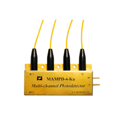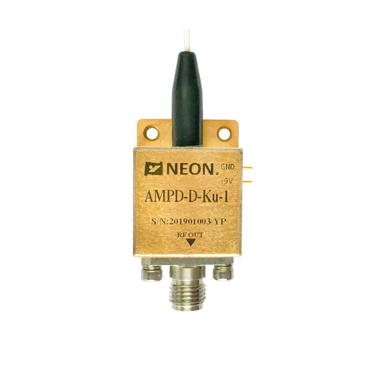

High Speed Photodetector Design: Overcoming Bandwidth Trade-offs
The rapid increase in the volume of information exchange worldwide calls for the continuous upgradation of optical transceivers to the order of 800 Gbps, 1.6 Tbps, and above per channel. In the IMDD and coherent optical communication schemes, the performance of the PD is highly important in the design of the optical receiver front end. High speed photodetectors are optoelectronic components that can convert optical signals into electrical ones at microwave/millimeter wave frequency range.
As signaling formats migrate from non-return-to-zero (NRZ) to higher-order pulse amplitude modulation (such as PAM4 or PAM8) and quadrature amplitude modulation (QAM), the requirements for higher bandwidth, lower noise, and higher power handling become more stringent. This technical analysis evaluates the fundamental metrics, advanced device topologies, packaging limitations, and characterization methods of high speed photodetectors operating in the millimeter-wave regime.
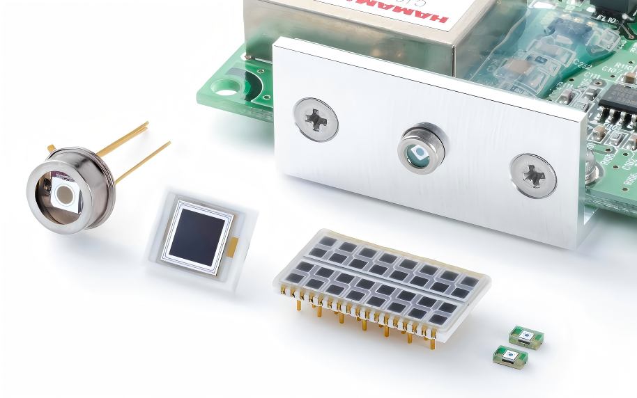
Key Figure-of-Merit Metrics for High Speed Photodetectors
Evaluating high speed photodetector performance requires an analysis of mutually dependent physical metrics. Optimizing a device for one metric frequently degrades another, establishing a rigid design trade-off matrix.
3dB Bandwidth (f3dB )
The 3dB bandwidth is the frequency at which the electrical power output of the photodetector drops to half of its low-frequency value. The total bandwidth is determined by the combination of three primary physical time constants, represented by the following relation:
1/f23dB≈1/f2RC+1/f2transit
- RC Delay Time (τRC): Formulated as τRC=(Rs+RL)Cj, where Rs is the series resistance of the diode, RL is the load resistance (typically 50Ω), and Cj is the junction capacitance. To reduce Cj, the active area A must be scaled down since Cj=ϵA/d, where d is the thickness of the depletion layer.
- Carrier Transit Time (τtransit): The time required for photogenerated electrons and holes to drift across the depletion region under an applied electric field. To reduce τtransit, the depletion layer thickness d must be minimized. This directly conflicts with the condition required to lower Cj, forming the fundamental bandwidth trade-off.
- Avalanche Multiplication Response Time: For Avalanche Photodiodes (APDs), the avalanche build-up time adds an extra delay due to the secondary ionization processes inside the multiplication layer, limiting standard APD bandwidths compared to PIN topologies.
Responsivity (R) & Quantum Efficiency (η)
Responsivity defines the conversion efficiency of optical power to electrical current, expressed as R=Ip/Pin=ηq/hν, where Ip is the photocurrent, Pin is the incident optical power, q is the electron charge, h is Planck’s constant, and ν is the optical frequency.
The internal quantum efficiency η depends on the optical absorption coefficient α and the absorption layer thickness d, given by η≈1−e−αd. Thick absorption layers maximize η and responsivity R but increase carrier transit time τtransit, thereby lowering the f3dB bandwidth. This is known as the classic Bandwidth-Efficiency Trade-off.
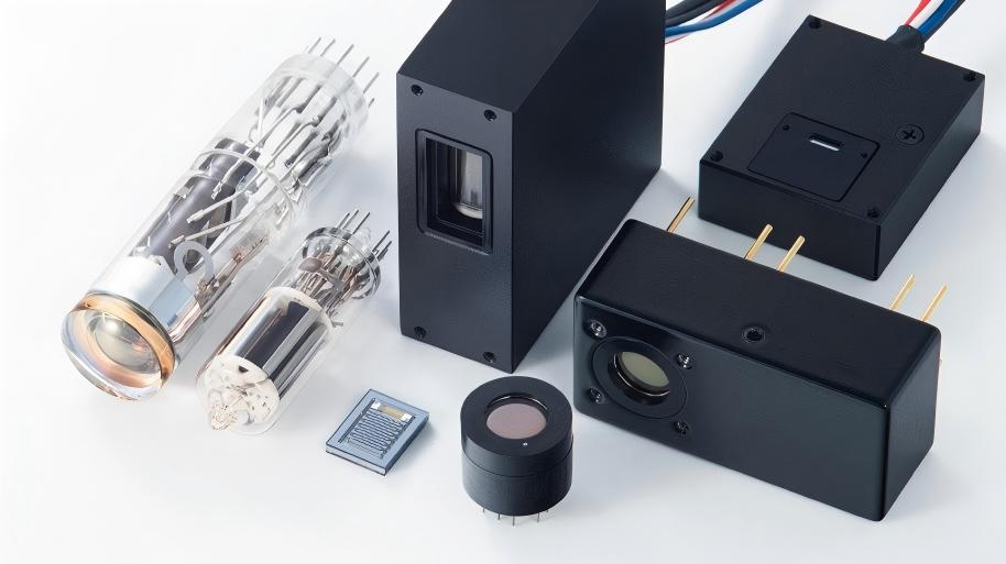
Dark Current (Id) & Noise Equivalent Power (NEP)
Dark current is the residual current flowing through the photodetector in the absence of incident light under a reverse bias voltage. Sources of dark current include bulk leakage (generation-recombination centers within the depletion region) and surface leakage current. High dark current increases shot noise, which directly degrades the Noise Equivalent Power (NEP) and lowers the overall signal-to-noise ratio (SNR) of the receiver.
Advanced Device Architectures: Beyond Standard PIN
To circumvent the rigid bandwidth-efficiency trade-off inherent in standard vertical PIN photodiodes, alternative structural architectures have been developed.
Uni-Traveling-Carrier Photodiode (UTC-PD)
The UTC-PD utilizes only electrons as active carriers to achieve high bandwidth and high saturation current. In a standard PIN PD, holes move at a drift velocity approximately 3 to 4 times slower than electrons in III-V semiconductors (such as InGaAs/InP), generating a space-charge effect that screens the internal electric field and causes saturation.
In a UTC-PD, the absorption layer is p-type doped. Photo-generated holes relax as majority carriers within the p-contact within picoseconds. Photogenerated electrons diffuse in a wider bandgap, undoped drift region, where they move at high velocities due to overshoot. The absence of carriers other than the electrons makes it possible to eliminate the influence of the space charge effect in UTC-PDs, and hence, bandwidth exceeding 100GHz.
Modified UTC-PD (MUTC-PD)
In the MUTC-PD, a thin intrinsic absorption layer is inserted between the p-type absorption layer and the n-type drift layer. This modification optimizes the electron injection profile in the drift layer, reducing the carrier accumulation at the heterojunction interface. MUTC-PDs are deployed in microwave photonics to generate high-power radio-frequency (RF) signals directly via optical heterodyning.
Waveguide Photodetector (WG-PD)
The Waveguide Photodetector detaches the optical absorption path from the electrical carrier collection path. Optical signals are coupled horizontally along the waveguide axis, allowing the absorption length to be long enough to achieve high quantum efficiency η. Simultaneously, the vertical thickness of the absorption layer can be kept small to minimize carrier transit timeτtransit.
Integration & Packaging Challenges at 100 GHz+
As physical operating frequencies scale past 100GHz, optical packaging and electrical parasitics become dominant limiting factors of system performance.
Optical Coupling & Alignment
High speed photodetectors designed for frequencies above 50GHz possess small active area diameters, often between 5μm and 20μm. In free-space applications, such as Over-the-Air (OTA) wireless optical testing, spatial beam drift or sub-micron mechanical misalignments induce severe coupling efficiency fluctuations. Precise lens configurations, such as aspheric lenses or collimator arrays with rigid optomechanical sub-mounts, are required to sustain stable optical interfaces.
RF Impedance Matching & Parasitic Effects
The electrical output path from the photodetector chip to the external circuit must maintain a continuous 50Ω characteristic impedance. Conventional wire-bonding has parasitic inductance (≈1nH/mm), which causes impedance mismatches and attenuation of high-frequency electrical signals. At frequencies above 100GHz, wire bonds must be replaced by the use of flip-chip bonding with micro-bumps or integrated coplanar waveguides (CPW) on sub-mounts to control parasitic capacitance and inductance.
Thermal Management
High-power operation and high dark currents generate localized thermal dissipation inside the sub-micron scale junction. The responsivity of materials like InGaAs changes with temperature due to bandgap shifting (ΔEg/ΔT). Active thermal management via Thermoelectric Coolers (TEC) integrated into the butterfly, or coaxial package, is mandatory to stabilize the operating temperature to within ±0.1 ℃.
Testing and Measurement Characterization Setup
Accurate characterization of high speed photodetectors requires calibrated millimeter-wave test configurations to separate device performance from system instrumentation artifacts.
Frequency Domain Measurement
The standard system for measuring f3dB bandwidth is a Lightwave Component Analyzer (LCA). The LCA modulates an optical carrier with an RF signal via an electro-optic modulator, sends the signal to the photodetector, and measures the output electrical power using an integrated vector network analyzer (VNA).
The optical heterodyne technique is utilized for frequencies higher than the capability of commercial LCAs (above 110GHz). Two independent continuous wave (CW) lasers are combined. The offset in wavelength (Δv=∣ν1−ν2∣) determines the beat frequency, which produces a stable RF signal sweeping over the photodetector bandwidth.
Time Domain Measurement
The time-domain measures are evaluated employing a very fast femtosecond pulse laser source with a sampling oscilloscope/TDR (Time Domain Reflectometer). It is important that the laser pulse width should be less than the expected response time of the detector (less than 100fs), in order to create a Dirac Delta function impulse. This configuration evaluates the pulse response full-width at half-maximum (FWHM) and isolates impedance discontinuities along the internal transmission lines.
OTA Testing Stability Optimization Techniques
When evaluating photodetectors in open-space Over-the-Air (OTA) configurations, mechanical and environmental stabilization protocols are required to minimize data variance:
- Automated Micro-Alignment: Implementation of computer-controlled six-axis alignment stages using gradient-seeking algorithms to continuously maximize DC photocurrent collection.
- Dynamic Range Optimization: Integrated inline, programmable Variable Optical Attenuators (VOA) are incorporated to maintain the incident power below the 1dB compression point (P1dB) of the integrated Transimpedance Amplifier (TIA).
- Stray Light Mitigation: Enclosure of the optical path within an anti-reflective, high-absorption dark box to suppress background ambient photon noise from terrestrial lighting.
Choosing the Right PD for Your Architecture
The selection of a photodetector topology depends on the operating frequency, link budget constraints, and manufacturing complexity of the targeted communication system.
| Detector Type | Target Bandwidth | Responsivity (A/W) | Primary Limitation | Ideal Application |
| Standard PIN | < 40 GHz | 0.7 – 0.9 | Bandwidth-Efficiency Trade-off | Datacom Short-Reach (SR4/LR4) |
| Waveguide PD | 40 – 100 GHz | 0.5 – 0.8 | Packaging Alignment Complexity | 800G/1.6T Coherent Optical Transceivers |
| UTC-PD | > 100 GHz | 0.2 – 0.4 | Low Optical Absorption Thickness | 6G Wireless Fronthaul / THz Generation |
Scaling optical receiver architectures to support higher baud rates requires photodetectors that operate beyond the 100GHz threshold without compromising responsivity. Advanced material platforms, such as graphene-silicon heterostructures, thin-film lithium niobate (TFLN) integration, and Ge-on-Si epitaxy, are under active development to replace conventional III-V vertical structures.