
10 Common InGaAs Photodetector Problems and How to Fix Them
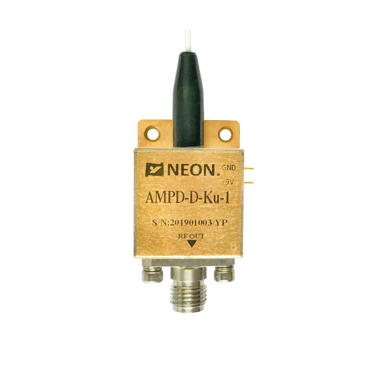
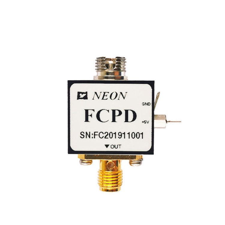
The InGaAs photodetector is an important device for converting optical signals into electrical current, and it is used in high-speed optical communications, short-wave infrared (SWIR) spectroscopy, and laser characterization. Despite the high quantum efficiency of an InGaAs photodetector at 900 nm to 1700 nm, it is subjected to various performance degradations when integrated into complex optoelectronic circuits.
If you’re designing or maintaining optical systems, it’s critical that you understand photodetector problems to ensure signal integrity. This technical guide discusses ten common failure modes that are encountered in troubleshooting InGaAs photodetectors and provides engineering solutions to improve performance.
1. High Dark Current and Noise Floor Elevation
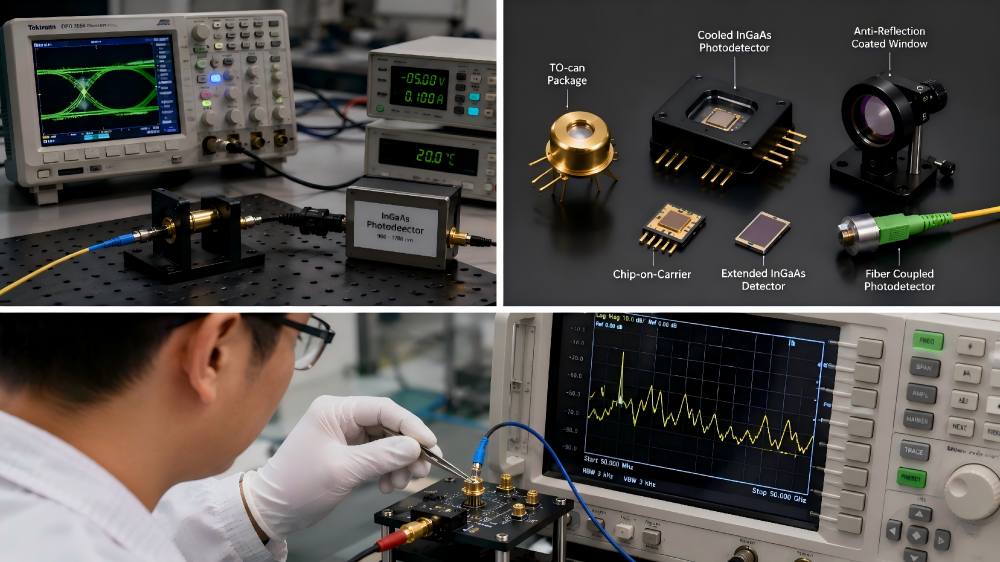
The excess dark current of photodiodes directly degrades the signal-to-noise ratio (SNR) of an optical system. Dark current is the reverse leakage current through the InGaAs photodetector junction in the complete absence of incident light.
The Cause: This is typically due to high ambient temperatures or too high a reverse bias voltage. InGaAs photodiode has a narrow bandgap (0.75 eV for standard In0.53Ga0.47As), which makes it very sensitive to thermal generation-recombination currents.
The Solution for Photodetector Noise Reduction: Use active thermal management with a Thermoelectric Cooler (TEC). By lowering the operating temperature, the thermal generation of electron-hole pairs is reduced. Also, the reverse bias voltage should be reduced to the minimum value necessary to maintain the required photodetector bandwidth so that surface leakage current is limited.
2. Optical Receiver Saturation and Nonlinearity
When an InGaAs photodetector operates outside its linear dynamic range, the output signal exhibits flattened peaks, leading to harmonic distortion in analog applications and bit error rate (BER) spikes in digital links.
The Cause: High incident optical power generates a carrier density that exceeds the capacity of the depletion region. This creates space-charge effects that screen the internal electric field. Alternatively, the output current may saturate the transimpedance amplifier (TIA) stage within an optical receiver.
The Fix: Attenuate the incoming optical signal using a fixed or variable Neutral Density (ND) filter before it reaches the InGaAs photodetector active area. If the spatial profile allows, slightly expand the optical beam to distribute the optical power density across the active area, preventing localized saturation.
3. Limited Bandwidth and Slow Response Time of Photodetectors
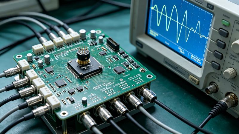
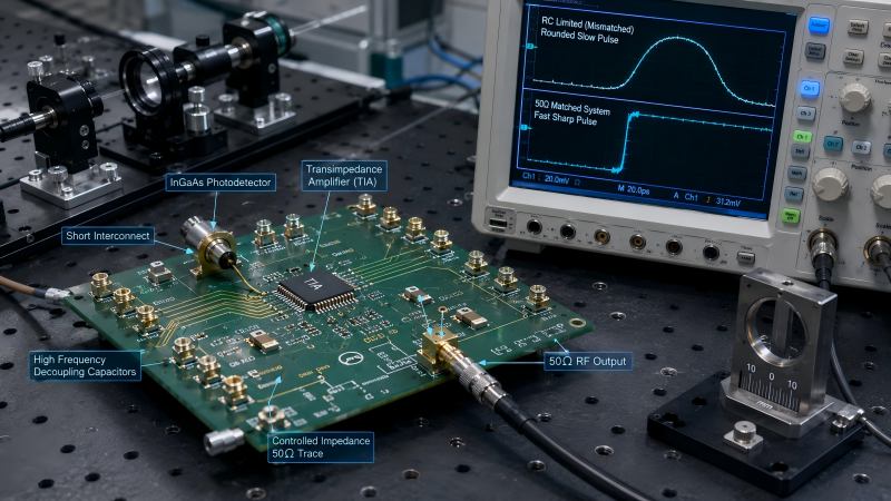
A high speed photodetector must resolve fast optical transitions. When a fast pulse appears rounded or asymmetric on an oscilloscope, the device is not meeting its bandwidth specifications.
The Cause: The primary limiters of photodetector bandwidth are the transit time of carriers across the depletion layer and the RC time constant of the circuit. Selecting an InGaAs photodetector with an excessively large active area increases the junction capacitance (Cj). Low reverse bias voltage also prevents the depletion width from reaching its optimal thickness.
The Fix: Increase the reverse bias voltage to expand the depletion region, which simultaneously reduces Cj and increases the drift velocity of photogenerated carriers. Ensure strict impedance matching between the InGaAs photodiode and the load resistor (RL), typically matching to a 50 Ω RF environment to minimize the RC time constant bottleneck.
4. High Fresnel Reflection Losses
Lower-than-expected photodetector responsivity across the target spectrum often indicates that a significant fraction of incident photons is reflecting off the detector surface rather than penetrating the semiconductor junction.
The Cause: Indium Gallium Arsenide possesses a high refractive index (n≈3.5 at 1550 nm). When light transitions from air (n=1) to the semiconductor surface, the index mismatch causes substantial Fresnel reflection losses (up to 30%).
The Fix: Ensure the InGaAs photodetector features an anti-reflection (AR) coating optimized for your specific operational wavelength (such as 1310 nm or 1550 nm). For free-space setups, tilt the detector assembly by 5° to 10° relative to the optical axis to prevent reflected light from traveling back into the optical source and causing laser instability.
5. Spatial Non-Uniformity of Responsivity
Spatial non-uniformity occurs when the electrical output of the InGaAs photodetector changes significantly as the incident light beam shifts across different positions of the active area.
The Cause: This problem is generally caused by surface contamination, such as dust particles or volatile organic compounds on the window cap, or localized crystalline defects introduced during epitaxial growth.
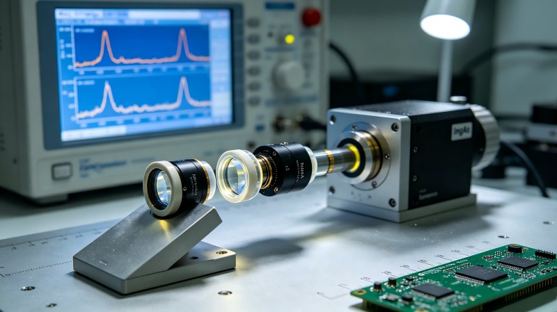
The Fix: Perform physical inspection and cleaning of the optical window using spectroscopic-grade isopropyl alcohol (IPA) and a lint-free optical swab. Mount the detector housing onto a precision X-Y translation stage to ensure the optical beam remains precisely centered on the active area of the InGaAs photodiode.
6. Shunt Resistance Degradation
The decrease of the shunt resistance (Rsh) results in an increase of the low-frequency noise and thermal instability, especially when the device is used in the photovoltaic (zero-bias) mode.
The Cause: Mechanical stress during mounting or moisture ingress through a compromised package seal can degrade the passivation layer protecting the perimeter of the semiconductor mesa.
The Fix: Use a hermetically sealed TO-can or ceramic package with dry nitrogen purge for components in harsh environments. Do not over-tighten mechanically during installation to prevent stress cracks in the chip passivation layer.
7. Thermal Responsivity Drift
Thermal responsivity drift causes inaccurate power measurements over extended operational periods, rendering the calibration data invalid.
The Cause: The bandgap energy of an InGaAs photodetector varies with temperature. As temperature increases, the absorption edge shifts toward longer wavelengths, directly altering the photodetector responsivity at the operational boundaries.
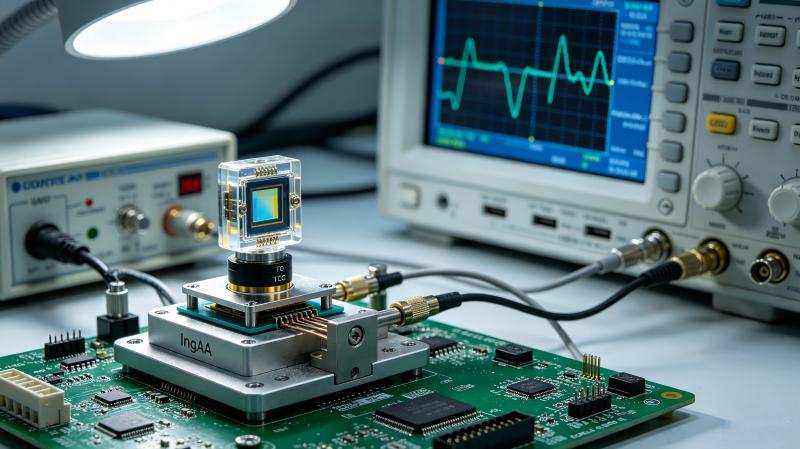
The Fix: Isolate the InGaAs photodetector from external temperature fluctuations by incorporating a closed-loop temperature control system. Utilize a thermistor embedded near the photodiode chip to provide feedback to a TEC controller, maintaining the detector at a stable baseline temperature (e.g., 20℃).
8. Catastrophic Optical Damage (Burn-In)
Catastrophic optical damage causes an immediate failure of the component, manifested as a short circuit or a massive permanent increase in dark current in photodiodes.
The Cause: High peak power pulsed lasers (Q-switched, mode-locked, etc.) can locally melt the semiconductor lattice if the optical damage threshold of the material is exceeded.
The Fix: Always compute the peak power density (W/cm2) instead of depending on average power metrics. Incorporate optical attenuators or optical limiters in front of the fibre optic detector front end. Use a mechanical safety shutter that blocks the beam path when the system is not in active data collection.
9. Output Signal Ringing and Electrical Oscillations
High-frequency ringing or impedance reflections on the rising and falling edges of transient pulses degrade the accuracy of time-resolved measurements in a high speed photodetector.
The Cause: Parasitic inductance from long electrical leads or poor printed circuit board (PCB) layouts forms a resonant tank circuit with the internal capacitance of the InGaAs photodiode.
The Fix for Optical Receiver Troubleshooting: Optimize the PCB layout by placing the transimpedance amplifier as close as possible to the InGaAs photodetector pins to minimize trace inductance. Install high-frequency ceramic decoupling capacitors immediately adjacent to the bias pins to filter out power supply transients and suppress parasitic oscillations.
10. Mismatch of Long Wavelength Cut-off
A complete lack of signal detection when measuring wavelengths beyond 1700 nm indicates a material cut-off limitation.
The Cause: Lattice-matched In0.53Ga0.47As grown on InP substrates has an intrinsic long-wavelength cut-off at approximately 1.7 μm. It cannot absorb photons with energies below its bandgap.
The Fix: For applications that require detection up to 2.2 μm or 2.6 μm, replace the standard component with an Extended InGaAs photodetector. Extended InGaAs adopts a higher indium content layer structure to reduce the bandgap energy. The extended versions show increased baseline noise, demanding more potent thermoelectric cooling for effective functionality.
Quick Troubleshooting Summary for InGaAs Detectors
The following matrix provides a diagnostic summary and corresponding engineering solutions for maintaining an InGaAs photodetector within an optical receiver or free-space optical assembly.
| Symptom | Probable Root Cause | Corrective Engineering Action |
| Elevated Noise Floor | Thermal carrier generation / Excessive reverse bias | Integrate TEC cooling; decrease bias voltage to minimum spec limit |
| Output Clipping / Distortion | Optical saturation of the InGaAs photodiode | Insert ND filters; expand optical beam diameter across active area |
| Degraded Pulse Rise Time | High junction capacitance (Cj) / Circuit impedance mismatch | Increase reverse bias voltage; match circuit to a 50 Ω RF load |
| Low Responsivity Output | High Fresnel reflection at the air-semiconductor interface | Deploy optimized AR coatings; tilt detector housing 5∘ to 10∘ |
| Signal Ringing on Oscilloscope | Parasitic inductance in the amplifier interface | Shorten PCB traces; place ceramic bypass capacitors near pins |
| Zero Response Above 1.7 μm | Material bandgap limitation of standard InGaAs | Upgrade system to an Extended InGaAs photodetector |