
TFLN Modulator Testing: Vπ, Bandwidth, IL & ER Measurement
Testing a thin-film lithium niobate (TFLN) modulator is more than reading datasheet specifications. Engineers need to test the modulator to determine its behavior under actual optical and electrical conditions. The four parameters are the half-wave voltage (Vπ), electro-optic bandwidth, optical insertion loss, and extinction ratio (ER). They provide an alternative view of the modulator performance. However, results can be influenced by test equipment, reference conditions, and measurement method.
This Guide is about measuring a TFLN modulator in the lab: what is needed, how to actually make the measurement, and some typical errors.
What Performance Parameters Should You Test in a TFLN Modulator?
A TFLN modulator converts an electrical signal into optical phase or intensity changes through the electro-optic effect. Its performance should be evaluated through both electrical and optical measurements.
| Parameter | What It Measures | Common Unit |
| Half-wave voltage (Vπ) | Voltage required for a π phase shift | V |
| EO bandwidth | Frequency response of electrical-to-optical modulation | GHz |
| Insertion loss (IL) | Optical power lost through the device | dB |
| Extinction ratio (ER) | Difference between maximum and minimum optical output power | dB |
Not every parameter applies in the same way to every modulator. An intensity modulator like a Mach-Zehnder modulator (MZM) would allow measuring the optical transfer curve and DC extinction ratio. A pure phase modulator alters the optical phase but not the optical intensity in a direct manner. However, since they are used to measure phase response should involve interferometric schemes or other phase-sensitive techniques to be measured.
Before testing, confirm the device type, operating wavelength, RF configuration, and measurement conditions.
What Equipment Do You Need for TFLN Modulator Testing?
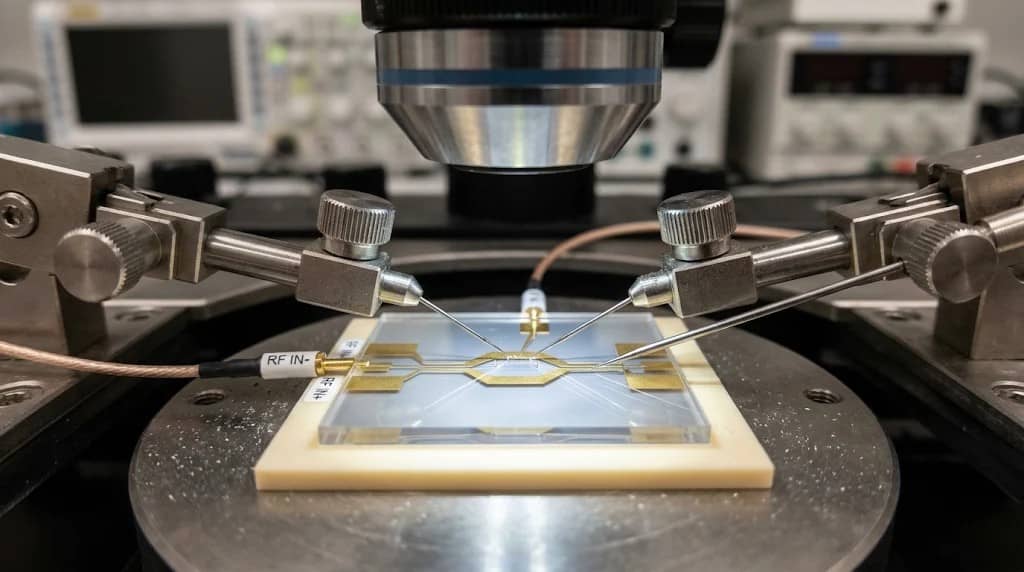
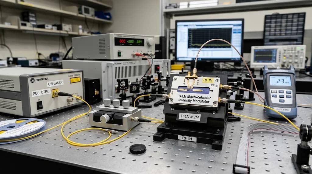
A typical TFLN modulator characterization setup combines optical power measurement with RF signal analysis.
| Equipment | Main Function |
| CW Laser | Provides a stable optical input |
| Polarization Controller | Adjusts the input polarization |
| Optical Power Meter | Measures optical input and output power |
| Vector Network Analyzer (VNA) | Measures RF S-parameters and EO frequency response |
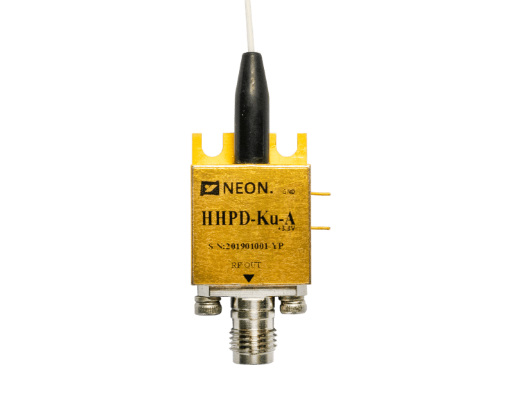
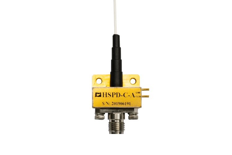
| High-Speed Photodetector | Converts modulated optical signals into electrical signals |
| RF Signal Generator | Supplies the required electrical drive signal |
| DC Bias Supply or Controller | Controls the modulator operating point |
| RF Cables and Probes | Connect the RF test path |
For EO bandwidth measurements, the typical connection is:
CW Laser → Polarization Controller → TFLN Modulator → High-Speed Photodetector → VNA Receiver
The VNA source connects to the modulator’s RF input. For static measurements, an optical power meter or a suitable photodetector can be used to monitor the output. Before testing, clean the optical connectors, inspect the RF connections, and allow the laser and measurement instruments to stabilize.
Use the correct optical wavelength, polarization, impedance, and RF power for the specific device. Never exceed its specified maximum operating ratings.
How to Measure the Half-Wave Voltage (Vπ)
The half-wave voltage is one of the key parameters of a TFLN modulator. It describes the voltage change required to produce a π-radian phase shift under specified drive conditions. For an intensity modulator, this phase change produces a measurable variation in output optical power.
Measurement Procedure
- Connect a stable CW laser to the modulator input.
- Adjust the polarization to achieve stable optical transmission.
- Connect a low-frequency signal source to the RF electrode and establish the required bias condition.
- Apply a triangular voltage sweep within the device’s operating limits.
- Record the output optical power as the applied voltage changes.
- Plot the voltage-versus-optical-power transfer curve.
- Identify adjacent transmission maximum and minimum points to determine Vπ according to the device’s drive configuration.
For a conventional single-arm MZM voltage convention, the voltage difference between adjacent transmission maximum and minimum points corresponds to Vπ.
The drive configuration matters. Single-drive, push-pull, and dual-drive modulators can use different voltage conventions. Always follow the manufacturer’s definition when reporting Vπ.
What Can Affect the Result?
Several factors can cause measured Vπ to differ from the datasheet value:
- RF cable and connector losses
- Impedance mismatch
- Polarization misalignment
- Temperature changes
- Bias instability
- Incorrect voltage measurement at the device input
For example, a signal generator’s displayed voltage may not represent the actual voltage delivered to the modulator electrode. Calibration and impedance conditions must be considered.
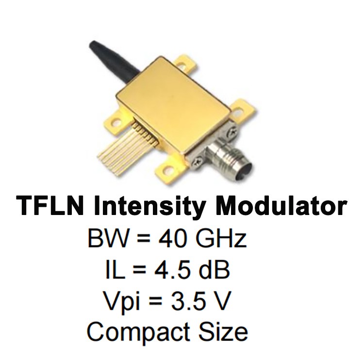
NEON specifies RF Vπ at 50 kHz for its TFLN Intensity Modulator. This provides a useful reference when setting up a comparable low-frequency measurement.
How to Measure the Electro-Optic (EO) Bandwidth
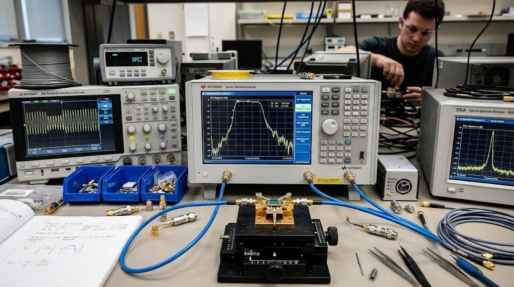
EO bandwidth describes how the modulator responds to electrical signals across different frequencies. The 3 dB bandwidth is a commonly reported performance indicator. A VNA-based measurement is widely used for high-speed TFLN characterization.
Measurement Procedure
- Connect a stable CW laser to the modulator through a polarization controller.
- Connect the VNA source to the modulator RF input.
- Connect the modulated optical output to a high-speed photodetector.
- Connect the detector’s RF output to the VNA receiver.
- Calibrate the RF measurement path and account for cable, fixture, and detector responses.
- Sweep the required frequency range and record the S21 response.
- Normalize the response to the specified reference level.
- Identify the frequency at which the response reaches the defined 3 dB roll-off point.
The measured EO S21 response includes the effects of the measurement system, not just the modulator. Detector bandwidth limitations, RF cable losses, and connector reflections can distort the result.
How to Interpret the S21 Curve
A useful frequency-response curve should show:
- The reference frequency and normalized response.
- The relatively flat operating region.
- Any noticeable response peaks or ripple.
- The 3 dB roll-off point.
- The frequency range covered by the measurement.
Do not confuse S21 with S11. S21 represents forward transmission response, while S11 describes RF input reflection. Both are useful, but they answer different questions.
Also check how the bandwidth is defined. NEON’s TFLN Intensity Modulator Die specifies its 3 dB bandwidth from 2 GHz. The measurement should therefore use a consistent reference rather than assuming a DC-to-3 dB definition.
How to Measure Optical Insertion Loss (IL)
Insertion loss measures the optical power reduction introduced by a modulator.
It is particularly important in optical communication and microwave photonic systems, where available optical power affects the downstream receiver and overall link budget.
The basic calculation is:
IL = 10 log₁₀(Pin / Pout)
Where:
- Pin is the reference optical input power.
- Pout is the measured optical output power.
Both power readings must use compatible reference planes and the same units.
Measurement Procedure
- Set the laser to the modulator’s specified operating wavelength.
- Measure the optical power at the defined input reference plane.
- Connect the laser to the modulator input.
- Measure the output optical power under stable operating conditions.
- Calculate insertion loss using the formula above.
- Repeat the measurement to check stability and repeatability.
Common Sources of Measurement Error
- Dirty optical connectors
- Fiber coupling loss
- Incorrect polarization
- Unstable laser output
- Different input and output reference planes
- Unaccounted connector or patch-cord losses
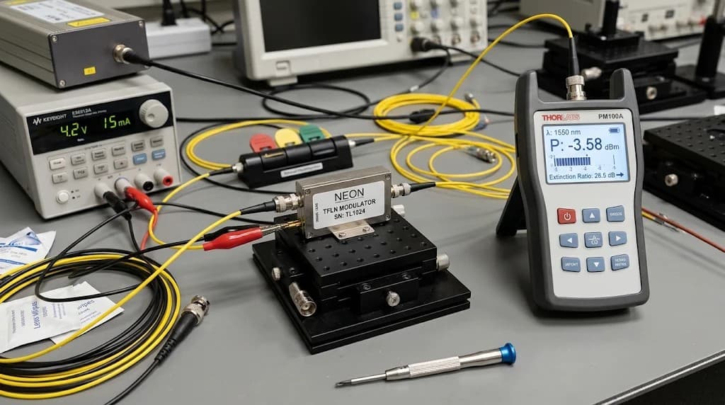
For packaged devices, distinguish the modulator’s insertion loss from external test-path losses. For a bare die, fiber-to-chip coupling loss may contribute significantly to the total measured loss. This distinction is important when comparing packaged TFLN Intensity Modulators with TFLN Intensity Modulator Dies.
How to Measure the Extinction Ratio (ER)
Extinction ratio describes the difference between the maximum and minimum optical output power of an intensity modulator.
It is commonly expressed in dB:
ER = 10 log₁₀(Pmax / Pmin)
Where:
- Pmax is the maximum measured optical output power.
- Pmin is the minimum measured optical output power.
Measurement Procedure
- Connect a stable laser to the modulator.
- Adjust the input polarization.
- Sweep the DC bias across the required operating range.
- Record the maximum and minimum optical output power.
- Calculate the extinction ratio.
- Repeat the measurement to check bias stability and consistency.
What Should You Check?
A low measured extinction ratio may result from:
- Incorrect DC bias
- Polarization mismatch
- Uneven optical splitting
- Optical power fluctuations
- Detector noise or insufficient measurement resolution
The measurement floor must be considered when the minimum optical power is very low. If the detector cannot reliably resolve Pmin, the calculated ER may not represent the actual device performance.
An important distinction is that DC extinction ratio and dynamic extinction ratio are not interchangeable. The former is measured with static bias, and the latter is associated with the optical levels as high-speed data is modulated.
A pure phase modulator also does not have an extinction ratio of intensity that can be measured directly as in a MZM. Its phase changes need to be converted to intensity changes by an interferometer.
Common TFLN Modulator Testing Problems and Troubleshooting
Unexpected measurements do not always indicate a faulty device. Engineers should first check the test configuration and measurement conditions.
| Problem | Possible Cause | Recommended Check |
| Vπ higher than expected | RF loss or impedance mismatch | Verify voltage at the device |
| Unstable Vπ readings | Bias or temperature drift | Stabilize operating conditions |
| Unexpected EO bandwidth roll-off | Detector or cable limitation | Check system response and de-embedding |
| Large S21 ripple | RF reflections | Inspect connections and S11 |
| High insertion loss | Fiber coupling or connector loss | Recheck reference planes and alignment |
| Low extinction ratio | Incorrect bias or polarization | Optimize bias and polarization |
A consistent test setup is essential for meaningful comparisons. Changing the laser wavelength, input polarization, RF reference plane, or measurement instrument can affect the reported results.
For further technical background on MZM transmission and modulator metrics, see the Ansys Optics MZM modulation response example.
How to Report TFLN Modulator Test Results
A useful characterization report should include more than four final numbers. It should document the conditions under which each result was obtained.
| Measurement | Information to Record |
| Vπ | Measured voltage, frequency, bias, and drive configuration |
| EO Bandwidth | S21 curve, reference frequency, and 3 dB point |
| Insertion Loss | Input/output power, wavelength, and reference planes |
| Extinction Ratio | Pmax, Pmin, bias condition, and detector measurement floor |
Also note the device model, serial number, operating temperature, polarization condition, RF impedance, and whether the instrument is calibrated. This will help normalize measurement conditions and allow comparison of the device and confirmation of deliveries for signs of changes in product development.
NEON offers several configurations for different electro-optic applications: Standalone TFLN Intensity Modulators with Integrated Light Sources, Intensity Modulators, Phase Modulators, and Modulator Dies. Engineers should refer to the product specifications to define their characterization procedures.
For an overview of how these parameters support device selection, see our related guide: TFLN Modulator Selection: Bandwidth, Vπ and Insertion Loss.
For further research on TFLN electro-optic characterization, see the study on ultra-broadband near- to mid-infrared electro-optic modulation.
The goal of TFLN modulator testing is not simply to obtain a set of performance numbers. It is to verify that the device delivers consistent optical and electrical behavior under clearly defined operating conditions.