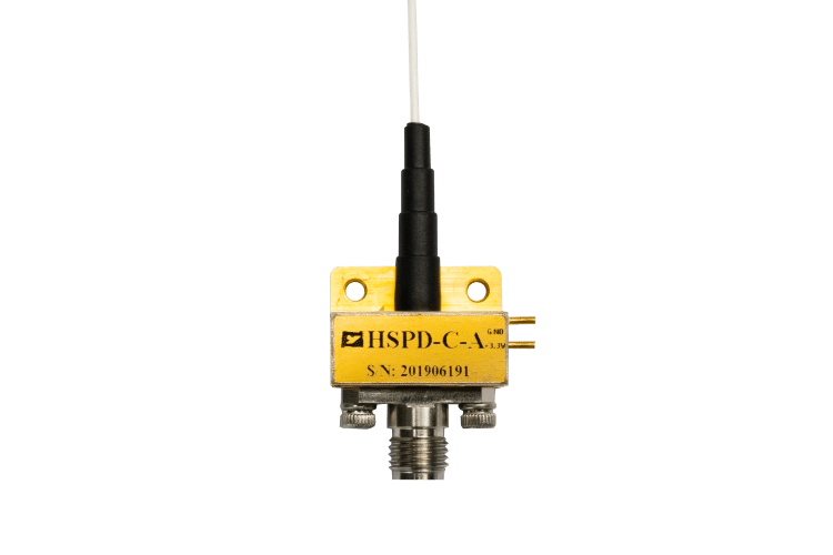

TFLN Modulator Selection: Bandwidth, Vπ and Insertion Loss
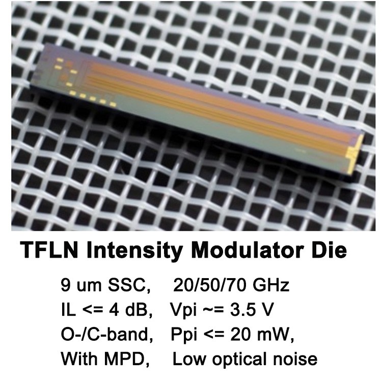
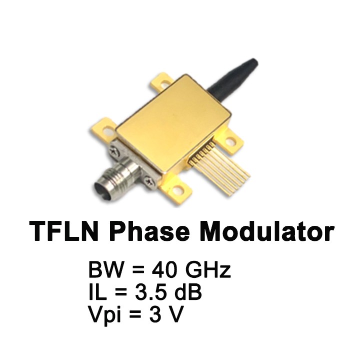
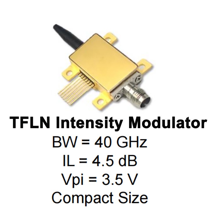
Selecting the appropriate thin-film lithium niobate (TFLN) modulator is not as easy as selecting bandwidth specs. The electro-optic bandwidth, half-wave voltage (Vπ), and insertion loss should be considered together to be compatible with the targeted optical or microwave photonic system.
The optical engineer, RF designer, and OEM developer should start the selection process with the application requirements. This guide shows how to evaluate these three key TFLN modulator specifications, compare datasheets, and avoid common selection mistakes.
Which TFLN Modulator Specs are Most Important?
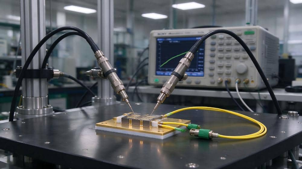
TFLN modulators modulate optical phase or intensity with an electrical signal utilizing the electro-optic effect of lithium niobate. The performance of the device depends on the modulation structure, the electrode design, optical coupling, and operating conditions.
| Specification | What It Measures | Why It Matters |
| Electro-optic bandwidth | Frequency response of the electrical-to-optical modulation process | Determines usable signal frequency range |
| Half-wave voltage (Vπ) | Voltage associated with a π phase shift under specified conditions | Helps determine driver voltage requirements |
| Insertion loss | Optical power lost through the device | Affects available optical power and link margin |
The best TFLN modulator might not be the one with the highest bandwidth or lowest Vπ. It is the apparatus that satisfies the application’s electrical, optical, and system-level requirements.
How to Measure TFLN Modulator Bandwidth
TFLN modulator bandwidth determines the device response to electrical signals over frequencies. The required bandwidth depends on the signal spectrum, the modulation format, and the system architecture.
A typical specification is the 3 dB electro-optic bandwidth. This is the frequency at which the measured response is 3 dB below the reference level. But that one number isn’t the entire story of the frequency response.
For a high-bandwidth TFLN modulator, look for:
- Operating frequency range: Does the device cover the whole desired signal band?
- Frequency response: Are there peaks or roll-offs that might impact signal fidelity?
- Electrode design: Is impedance matching and microwave-to-optical velocity matching enough?
- Measurement conditions: Were the frequency response and the reference planes consistent?
In microwave photonics and RF-over-fiber systems, the bandwidth has to be taken into account, together with link gain, noise and linearity. The modulation format and the transmitter architecture also affect the required performance for high-speed optical communication.
Selection tip: Before comparing candidate devices, determine the minimum usable bandwidth and acceptable response variation. Don’t choose a modulator just because its headline bandwidth is larger.
Comparison of TFLN Modulator Vπ and Drive Voltage
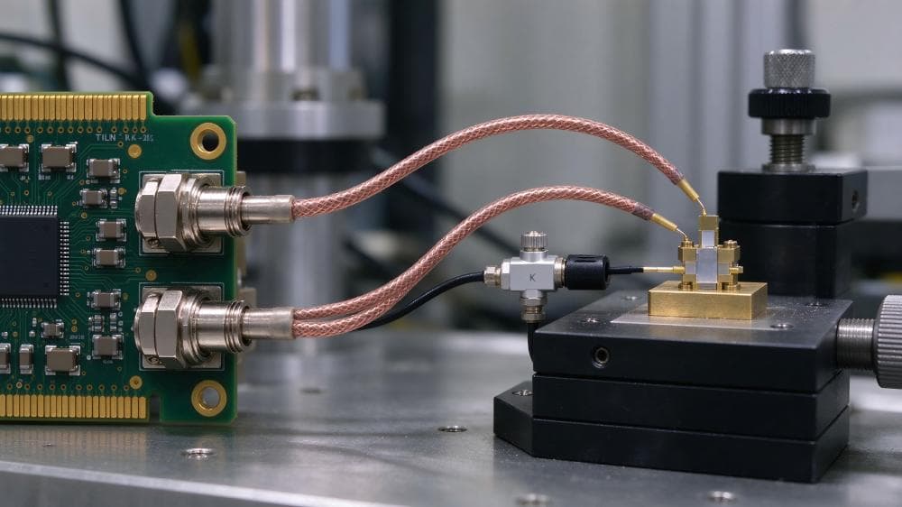
The half-wave voltage, Vπ, is the voltage necessary to create a phase shift of π radians in a phase modulator. It is usually the voltage required to cause a π differential phase shift between the optical arms of a Mach–Zehnder intensity modulator, according to the datasheet.
Lower Vπ can lead to lower drive voltage at a given modulation condition, but does not automatically mean lower total system power consumption.
The actual performance depends on the operating frequency, electrode configuration, electrical impedance, RF losses, and driver characteristics.
When selecting a low-Vπ TFLN modulator, consider:
- The driver provides a sufficient voltage swing for the target load.
- The specified Vπ is valid at the desired operating frequency.
- The modulator and driver are impedance and interface compatible.
- The measurement definition used in the specification is appropriate to the type of modulation.
Do not compare Vπ values from different datasheets without looking at the test conditions. A value measured at one frequency or termination condition may not be representative of performance in another system.
How to Measure TFLN Modulator Insertion Loss
Insertion loss is the loss in optical power due to the insertion of a device in an optical path. This is an important consideration when the laser power is limited, or the receiver requires sufficient optical signal margin.
The output optical power can be estimated as:
Output power (dBm) = Input power (dBm) – Insertion loss (dB)
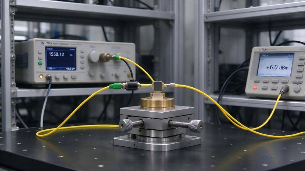
For example, with an input power of 10 dBm and an insertion loss of 4 dB, the output power would be taken to be 6 dBm, with no other losses.
Compare TFLN modulator insertion loss at the same measurement wavelength, polarization, coupling configuration and reference planes. These factors might influence direct comparability of published values.
Also differentiate between the specified insertion loss of the modulator and the total loss in the optical link. Fiber coupling, connectors, and other optical components can contribute additional loss.
Selection tip: Don’t treat the modulator’s insertion loss as the only loss in the system; do a full optical power budget.
How to Balance Bandwidth, Vπ, and Insertion Loss
The three specifications interact with various parts of the system. The limitations of the application form the basis for a balanced selection process.
| Application Priority | Parameters to Evaluate | Key Consideration |
| High-frequency operation | Bandwidth and frequency response | Confirm performance across the operating band |
| Lower drive requirements | Vπ and driver compatibility | Check actual voltage swing and electrical loading |
| Optical power efficiency | Insertion loss and link budget | Include coupling and connector losses |
| Overall system performance | Bandwidth, Vπ, loss, and linearity | Validate the device under intended operating conditions |
For instance, a microwave photonic system might place a premium on frequency response and linearity. If the transmitter has a limited optical power budget, it may be more concerned about insertion loss and available launch power.
Set minimum requirements for each critical parameter before you compare devices. This prevents an attractive value in one specification from obscuring a limitation elsewhere. Discover more system-level considerations such as frequency range, insertion loss, and amplitude flatness by exploring NEON’s optical delay line solutions for related microwave photonics applications.
A Practical Guide for TFLN Modulator Selection
Use this workflow to screen devices for a new design in optical or microwave photonics.
- Step 1: Define Application. Specify the type of signal, modulation scheme, frequency, and system architecture.
- Step 2: Determine bandwidth requirement. Determine the minimum usable and acceptable frequency-response variation in bandwidth.
- Step 3: Check Vπ and driver compatibility. Check voltage swing, impedance, and RF interface requirements
- Step 4: Calculate optical power budget. Modulator loss, fiber coupling, and optical components such as connectors are included.
- Step 5: Compare datasheets in a consistent way. Check frequency of measurement, wavelength, polarization, termination and reference planes
- Step 6: Verify system performance. Review the applicable test curves and check operation under the intended conditions.
For more information on electro-optic modulation, see the RP Photonics Encyclopedia article on electro-optic modulators. Find peer-reviewed papers in IEEE Xplore on lithium niobate device design and high-speed performance research.
Common Mistakes in TFLN Modulator Selection
Here are some pitfalls to avoid when choosing a TFLN modulator for high-speed use:
- Selection by maximum bandwidth only: Consider the full frequency response.
- Compare Vπ with no matching test conditions: examine frequency, modulation type, and termination.
- Ignoring the optical power budget: Consider the coupling and connector losses.
- Ignoring driver compatibility: Look for voltage swing, impedance, and RF interface requirements.
- Headline specifications only: Ask for supporting data and check on system level.
These checks allow engineers to determine if a candidate device is appropriate for the application, instead of just comparing products on a specification-by-specification basis.
Frequently Asked Questions
Q1: What is the bandwidth of a TFLN modulator?
The required bandwidth depends on the signal spectrum, the modulation format, and the application. Don’t rely on the maximum bandwidth stated on a data sheet. Evaluate the response over the operating range of interest.
Q2: What is the significance of Vπ in choosing a TFLN modulator?
Vπ is used to calculate the drive voltage required for modulation. A lower value may ease driver requirements, but frequency response, impedance, and actual operating conditions should also be taken into account.
Q3: How does insertion loss affect the performance of an optical link?
Insertion loss reduces the power available downstream. Include it in the link budget with coupling loss, connector loss, and other optical components.
Q4: Can a TFLN modulator have simultaneously high bandwidth and low Vπ?
Potentially, but the combination that can be achieved is dependent on the device design, electrode configuration, and operating conditions. Perform a comparison of specifications obtained under the same conditions and validate the whole system.