
How to Select an Optical Delay Line for RF and Microwave Applications
Selecting an optical delay line for an RF or microwave system is more than just meeting a delay time. The right device must simultaneously meet the application’s requirements for frequency range, delay range, delay accuracy, insertion loss, amplitude flatness, RF power, noise figure, VSWR, temperature stability, and mechanical integration.
For radar testing, phased-array systems, RF signal simulation, microwave photonics and antenna simulation, these parameters directly impact signal fidelity and system measurement accuracy. In practical terms, optical delay line selection should start with the RF frequency range and required delay, followed by delay accuracy, signal integrity, RF power handling, environmental stability, and integration requirements.
Define the RF Frequency Range and Required Delay
The first step in optical delay line selection is to establish the complete operating frequency range. An RF optical delay line should cover the application’s minimum and maximum RF frequencies with sufficient margin. Selecting a device whose upper frequency limit is close to the system’s operating frequency can leave little room for future upgrades or broadband testing.
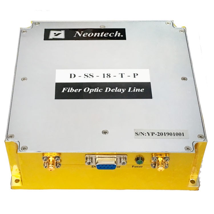
For example, NEON’s D-SS portfolio currently includes:
| Model | Frequency Range | Time Delay |
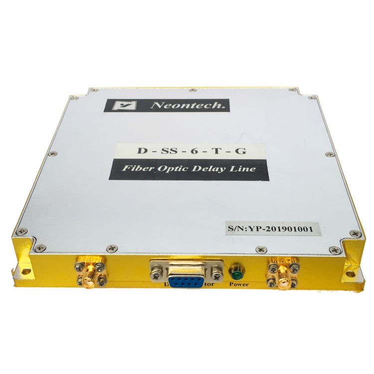
| D-SS-06-T | 0.1–6.5 GHz | 0.01–150 μs |
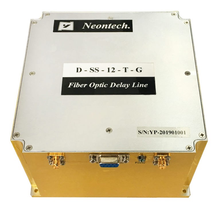
| D-SS-12-T | 1–12 GHz | 0.01–150 μs |
| D-SS-18-T | 2–18 GHz | 0.01–150 μs |
The D-SS-06-T product page also specifies a customized time-delay range of 0.01–150 μs, while the D-SS-18-T provides the same overall delay range for its 2–18 GHz configuration.
Calculate the required delay range
The required delay should be determined from the physical or simulated propagation path that the system needs to reproduce. For radar applications, the relationship between propagation delay and equivalent target range is approximately:
R = c × t / 2
where:
- R = equivalent radar target range
- c = speed of light
- t = round-trip delay
Therefore, a longer delay range enables simulation of greater equivalent target distances.
However, the required delay should not be selected independently from bandwidth. A delay line must maintain acceptable signal characteristics throughout the frequency and delay conditions required by the test system.
Evaluate Optical Delay Line Delay Accuracy and Stability
For precision RF simulation, the nominal delay value is only part of the specification. Optical delay line delay accuracy determines how closely the generated signal reproduces the intended propagation time. NEON’s D-SS-06-T, D-SS-12-T and D-SS-18-T specifications list a delay accuracy of ±5‰.
For radar testing, even a small delay error can translate into an equivalent range error. For example, if a system requires a highly repeatable simulated target distance, the delay line must provide not only the required nominal delay but also sufficiently stable delay under operating conditions.
Temperature stability also matters
Temperature can affect optical and electronic components and therefore change the effective delay. The D-SS-06-T and D-SS-18-T product specifications list relative delay versus temperature up to 7 ppm/°C.
Therefore, for outdoor radar testing, aerospace equipment, or systems operating across a wide temperature range, delay stability versus temperature should be included in the procurement specification rather than evaluating delay accuracy only at room temperature.
Check Insertion Loss, Amplitude Flatness and RF Signal Fidelity
After frequency and delay, the next major selection criteria are insertion loss and amplitude flatness.
Insertion loss
Insertion loss determines how much RF signal power is lost when the signal passes through the optical delay line. A high insertion loss may require additional amplification and can reduce the available system dynamic range.
NEON’s published specifications show customized insertion-loss ranges, with the D-SS-06-T listed at 0–20 dB maximum and the D-SS-18-T at 0–30 dB maximum.
For this reason, buyers should evaluate:
- Required input signal power
- Expected output signal level
- Available amplifier gain
- Receiver sensitivity
- Total system noise and dynamic range
Amplitude flatness
Optical delay line amplitude flatness describes how consistently the RF signal amplitude is maintained across the operating frequency range. A delay line with poor amplitude flatness can introduce frequency-dependent amplitude distortion, which may affect broadband radar signals, microwave measurements, and signal simulation.
The D-SS series specifies typical amplitude flatness of ±2 dB and maximum values of ±2.5 dB. For broadband applications, amplitude flatness should therefore be evaluated across the actual operating bandwidth, rather than based only on a single frequency point.

Match RF Power, Compression, VSWR and Noise Requirements
A suitable microwave optical delay line must also match the electrical characteristics of the RF system.
Input power and 1 dB compression
The input 1 dB compression point indicates when the device begins to exhibit significant gain compression as RF input power increases. For example, the published D-SS-06-T specification lists a typical input 1 dB compression point of 10 dBm, while D-SS-18-T lists 13 dBm typical.
When selecting an optical delay line for RF, compare: Maximum expected RF input power < appropriate compression limit. A sufficient power margin is particularly important for pulsed radar signals, high-power microwave testing, and systems with large signal-level variations.
VSWR and impedance
The RF interface should also match the system impedance. The D-SS series uses a 50 Ω RF interface, while published VSWR values vary by model.
Poor impedance matching can increase reflections and degrade overall system performance.
Noise figure
Noise figure becomes particularly important when the optical delay line is used in sensitive receiver paths. NEON lists noise figures of approximately 40–50 dB for the D-SS-06-T and 50–60 dB for the D-SS-18-T under the specified conditions.
For applications where receiver sensitivity is critical, a dedicated low-noise configuration should be considered rather than selecting a standard delay line solely from its delay and bandwidth specifications.
NEON also provides a low-noise optical fiber simulation and transmission solution for customized applications.
Choose Between Fixed and Variable Optical Delay Lines
Another important decision is whether the application requires a fixed optical delay line or a variable/customized delay solution.
| Requirement | Fixed Optical Delay Line | Variable Optical Delay Line |
| One predetermined delay | Excellent fit | May be unnecessary |
| Multiple simulated distances | Limited | Better suited |
| Automated test systems | Depends on architecture | More flexible |
| Repeatable fixed-delay testing | Suitable | Suitable |
| Multiple test scenarios | Requires multiple configurations | More convenient |
| Customized delay requirements | Available in selected configurations | Particularly useful |
A fixed delay line is appropriate when the test system repeatedly uses predetermined delay values. A variable optical delay line becomes more useful when the system needs to reproduce multiple propagation delays or dynamically change simulated target conditions.
NEON’s product portfolio identifies the D-SS-12-T as a variable optical delay line & optical simulator, while the D-SS-06-T and D-SS-18-T ordering information identifies fixed fiber-optic delay-line configurations with customized delay values. The choice should therefore be based on the test architecture rather than simply selecting the device with the largest delay range.
Match the Optical Delay Line to the RF Application
Different RF and microwave applications prioritize different specifications.
Radar testing and calibration
For radar test systems, prioritize:
- Frequency coverage
- Delay range
- Delay accuracy
- Temperature stability
- Amplitude flatness
- Dynamic range
The optical delay line for radar should reproduce the required propagation delay without introducing unacceptable amplitude or timing errors. NEON specifically lists radar testing and calibration among the applications of its D-SS optical delay line series.
Phased-array antenna systems
Phased-array applications require careful consideration of delay consistency between channels. An optical true time delay approach can provide actual propagation-time control rather than relying only on phase rotation. This makes delay accuracy, channel-to-channel consistency, amplitude flatness, and temperature stability important selection parameters.
RF signal and antenna simulation
For RF signal simulation, the delay line may need to reproduce different signal propagation conditions. In this case, buyers should consider:
- Delay range
- Frequency bandwidth
- Signal fidelity
- Insertion loss
- RF power handling
- Configuration flexibility
Low-noise RF receiving systems
When the delay line is placed in a sensitive receiver chain, noise performance becomes a primary consideration. A low-noise customized optical delay or transmission architecture may be more appropriate than a standard configuration.
Optical Delay Line Selection Checklist
The following checklist can be used when preparing an RF or microwave optical delay line specification.
| Selection Parameter | Key Question |
| Frequency range | Does the optical delay line cover the complete RF bandwidth? |
| Time delay | What minimum, maximum and nominal delays are required? |
| Delay accuracy | What timing error can the system tolerate? |
| Temperature stability | How much delay variation is acceptable across temperature? |
| Insertion loss | Can the RF chain compensate for the expected loss? |
| Amplitude flatness | Is signal amplitude sufficiently uniform across bandwidth? |
| Noise figure | Will added noise affect receiver sensitivity? |
| 1 dB compression | Can the device handle the maximum RF input power? |
| VSWR | Is the RF interface properly matched to the system? |
| Fixed/variable | Does the test system require one or multiple delay values? |
| Mechanical package | Does the module fit the available installation space? |
| RF connector | Does the connector match the existing RF architecture? |
| Temperature range | Does the device meet the system’s environmental requirements? |
| Customization | Are special delay, bandwidth, package or performance requirements needed? |
NEON Optical Delay Line Selection Guide
NEON’s current optical delay line portfolio can be matched to different RF and microwave requirements:
| Application Requirement | Relevant NEON Solution |
| 0.1–6.5 GHz RF delay | D-SS-06-T |
| 1–12 GHz variable delay | D-SS-12-T |
| 2–18 GHz microwave delay | D-SS-18-T |
| High-frequency radar testing | D-SS-12-T / D-SS-18-T |
| Fixed customized delay | D-SS series |
| Compact installation | Compact P configuration |
| Low-noise transmission/simulation | DS-LNF |
| Customized amplitude/phase stability | DS-HAP |
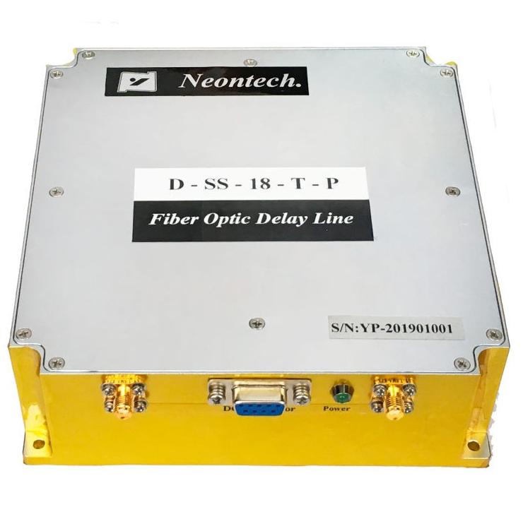
The D-SS-06-T supports 0.1–6.5 GHz, while the D-SS-18-T covers 2–18 GHz and provides customized delays from 0.01 to 150 μs. Both products also offer standard and compact structural configurations. For applications requiring specialized noise or amplitude/phase performance, NEON’s customized solutions can be considered in addition to the standard D-SS configurations.
Frequently Asked Questions
Q1: What is the most important specification when selecting an optical delay line?
A1: Start with the required RF frequency range and time-delay range, then verify delay accuracy, insertion loss, amplitude flatness, noise figure, RF power handling, VSWR, and temperature stability.
Q2: What delay accuracy is needed for radar testing?
A2: It depends on the required simulated range accuracy. Higher-precision radar testing generally requires tighter optical delay line delay accuracy and better temperature stability.
Q3: What is the difference between fixed and variable optical delay lines?
A3: A fixed optical delay line provides a predetermined delay, while a variable optical delay line supports multiple delay values for more flexible RF and radar test scenarios.
Q4: Why is insertion loss important?
A4: Insertion loss reduces RF signal power and can affect system dynamic range. It should be evaluated together with receiver sensitivity, amplifier gain, and overall signal levels.
Q5: Does temperature affect optical delay line performance?
A5: Yes. Temperature can affect delay and insertion loss. For outdoor, aerospace, and radar applications, temperature stability should be included in the selection criteria.
Q6: Can an optical delay line be customized?
A6: Yes. Depending on the application, the frequency range, delay, package, connector, temperature grade, and other performance requirements can be customized.