How to Align Optical Delay Line?
Modern optical systems rely heavily on an Optical Delay Line (ODL), an essential device that precisely controls optical path length and time delays. ODLs play an indispensable role in laser interferometry, optical communication, metrology or ultrafast laser systems; precise alignment of an ODL is imperative to successful experiments or devices functioning optimally.
How to align optical delay line? Here, we will offers step-by-step guidance and addresses any common issues to help ensure accurate, stable optical delay control for experiments or devices.
Part 1. What is an Optical Delay Line?
An Optical Delay Line (ODL) is a device used to control the propagation time of an optical signal by adjusting the length of its optical path. The fundamental principle involves manipulating the path that light travels, either in free space or through optical fiber—to introduce a precise time delay. This is typically achieved using movable mirrors, translation stages, or variable-length fiber loops, depending on the application.
There are two common types of optical delay lines:
1. Free-Space Optical Delay Lines
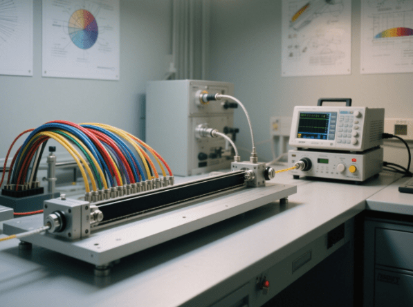
These systems use mirrors, lenses, or other reflective components to alter the distance light travels through air. By mechanically adjusting the position of the mirrors or the entire optical assembly, users can finely control the delay. This type of delay line is often used in high-precision laboratory setups, such as interferometry or ultrafast laser systems, due to its low dispersion and high accuracy.
2. Fiber-Based Optical Delay Lines
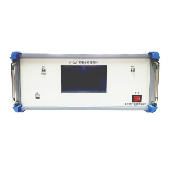
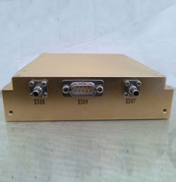
In fiber delay lines, the optical path is adjusted by increasing or decreasing the length of optical fiber that the light travels through. This method is compact, stable, and well-suited for applications in optical communication and signal processing. Some advanced systems use fiber coils or switchable segments to dynamically vary the delay over a broad range.
Each type has its own advantages and is chosen based on specific requirements for delay range, stability, precision, and system integration.
Part 2. Why is Precise Alignment of an Optical Delay Line So Important?
Accurate alignment of an optical delay line is critical to the functionality and stability of any optical system based on precise time control. Alignment guarantees that the optical beam has the best transmission efficiency, spatial quality, and timing accuracy. When the delay line misaligns, it may cause a series of issues that lead to system degradation, including:
1. Beam Misplacement and Energy Loss
A slight misalignment of the optical path will cause the output beam deflecting off-center or missing its intended destination altogether, leading to reduced signal intensity, compromised power efficiency, and potential misalignment with downstream devices.
2. Beam Divergence and Interference Instability
Misalignment generally causes beam divergence or incomplete overlap in interferometric arrangements, generating unstable interference fringes and oscillating signal outputs. Such instability is especially unwanted in applications like Michelson interferometers or ultrafast spectroscopy, where the stability of interference is paramount.

3. Reduced Timing Accuracy
The primary function of a delay line is to control the exact timing of the light signal. If the alignment is off, the physical distance the light travels may differ from the intended design, leading to inaccurate delay values and poor time resolution in measurement or signal control.
4. Lack of Repeatability and Limited Scalability
There is no repeatability in alignment, and outcomes fluctuate from run to run or setup to setup, reducing the repeatability of experiments or device operation. The system cannot be scaled for production deployment or extended deployment because of this unreliability.
For all these applications, a precise, stable, and repeatable alignment process is not only beneficial but essential. This enables the optical delay line to perform stably, provide the intended delay with high accuracy, and be included in complex optical systems in research and industry.
Part 3. How to Align an Optical Delay Line?
Precise alignment of an optical delay line is vital to ensure reliable operation, correct time delay, and system stability. The steps below are a step-by-step comprehensive guide to assist you in aligning your optical delay line correctly for optimum performance.
Step 1: Preparation and Installation
Begin by mounting the optical delay line on a vibration-minimizing optical table, breadboard, or linear translation stage to keep it stable and minimize mechanical drift. Ensure that the mirrors, beam splitters, lenses, or fiber couplers are clean, well-mounted, and free of dust or contamination.
- Mount the delay line so that its optical axis aligns roughly with the rest of your optical system.
- Connect the laser source to the input side and the detector or sensor to the output side, according to the manufacturer’s guidelines.
- Make sure that all movable parts (e.g., translation stages or rotating mirrors) function smoothly and have proper mechanical range for delay adjustment.
Step 2: Coarse Optical Alignment
Turn on the laser or light source and perform a preliminary check to verify that the beam can pass through the delay line.
- For free-space delay lines, ensure that the beam enters the first mirror or lens, reflects along the intended path, and reaches the output side. In setups with retroreflectors or corner cubes, check that the returning beam overlaps with the incoming path.
- In interferometric applications, look for initial interference fringes or beam overlap patterns on a screen or sensor, even if they are not yet perfectly clear.
- For fiber-based delay lines, ensure that the light is successfully coupled into and out of the fiber ports, with acceptable insertion loss.
Step 3: Fine Alignment of the Optical Path
Once the coarse alignment is complete, fine-tune the beam path using precision adjustment tools.
- Use kinematic mirror mounts or micrometer-driven stages to finely adjust the mirror angles and positions.
- Observe the beam on a beam profiler, IR viewer, or target screen and center the spot to the desired location. The ideal spot should be symmetrical, stable, and without significant distortion.
- In interferometric systems, maximize the visibility and contrast of interference fringes, which indicates optimal optical path overlap.
- If using a power meter or photodetector, adjust for maximum output intensity, which typically coincides with best alignment.
Step 4: Verify Alignment Quality and Delay Performance
After alignment appears optimal, thoroughly test the delay line across its entire travel range to ensure consistent performance.
- Move the delay line through different positions (e.g., sliding the stage or rotating mirrors), and monitor the beam position and output power at each point.
- Check for beam walk-off (i.e., lateral displacement) and signal fluctuations—both should be minimal.
- If possible, use a data acquisition system to log output power at various delay positions. This helps establish a performance baseline and identify any mechanical or optical anomalies.
Step 5: Lock the Setup and Ensure Long-Term Stability
Once the system is properly aligned:
- Tighten all adjustable mounts and mechanical components to prevent drift due to vibrations, thermal expansion, or accidental touches.
- Add reference marks, position encoders, or scale indicators on the translation stage to simplify future repositioning or realignment.
- For critical systems, consider environmental isolation (e.g., enclosures, thermal shielding) to maintain alignment over time.
Part 4. Common Issues and Troubleshooting in Optical Delay Line Alignment
During the alignment and operation of optical delay lines, users may encounter a variety of issues that impact performance. Below is a table outlining some of the most common problems, their likely causes, and effective solutions—with slightly more detailed explanations for clarity.
| Problem | Possible Cause | Suggested Solution |
| Beam spot shifts or is unstable | Inaccurate alignment; mechanical components not secured | Recheck and fine-tune the mirror angles using micrometer mounts; firmly tighten all mounting hardware to eliminate play or vibration. |
| Significant drop in optical power | Mirror angle deviations; dust or smudges on optics | Clean all optical surfaces (mirrors, lenses) with appropriate wipes or solvents; use a laser alignment tool to recalibrate mirror angles. |
| No response after adjustment | Movement stage or motor not coupled to mirror mount | Inspect whether the translation stage or actuator is properly driving the mirror assembly; check for mechanical coupling or software control errors. |
| Blurry or unstable interference fringes | Beam paths are not collinear; mirror surfaces are uneven or misaligned | Use alignment tools (e.g., alignment laser, irises) to ensure optical axes are properly aligned; fine-tune mirror pitch and yaw to achieve clean, stable fringe patterns. |
Part 5. How to Choose an Optical Delay Line?
When selecting an optical delay line, “ease of alignment” is a crucial factor, especially in applications that demand high precision and stability. The following aspects can serve as key criteria when evaluating ease of alignment:
1. Rational Structural Design
An easy-to-align optical delay line should feature a modular design, a stable optical path structure, and a mechanical system that supports repeatable positioning. These features significantly reduce the time required for initial setup and ongoing maintenance.
2. Precision of Mirror or Fiber Path Adjustment
Whether the device is equipped with high-precision translation stages, fine-adjustment mirror mounts, or motorized control mechanisms directly affects how efficiently and accurately the optical path can be adjusted.
3. Built-In Alignment Reference Mechanisms
Integrated features such as reference laser lines, graduated scales, or encoder feedback help users quickly pinpoint the beam position and enhance repeatability across different setups.
4. User Experience and Support
Ease of use also depends on whether the product comes with clear installation guides, technical documentation, and responsive after-sales support. These resources are key indicators of a user-friendly system.
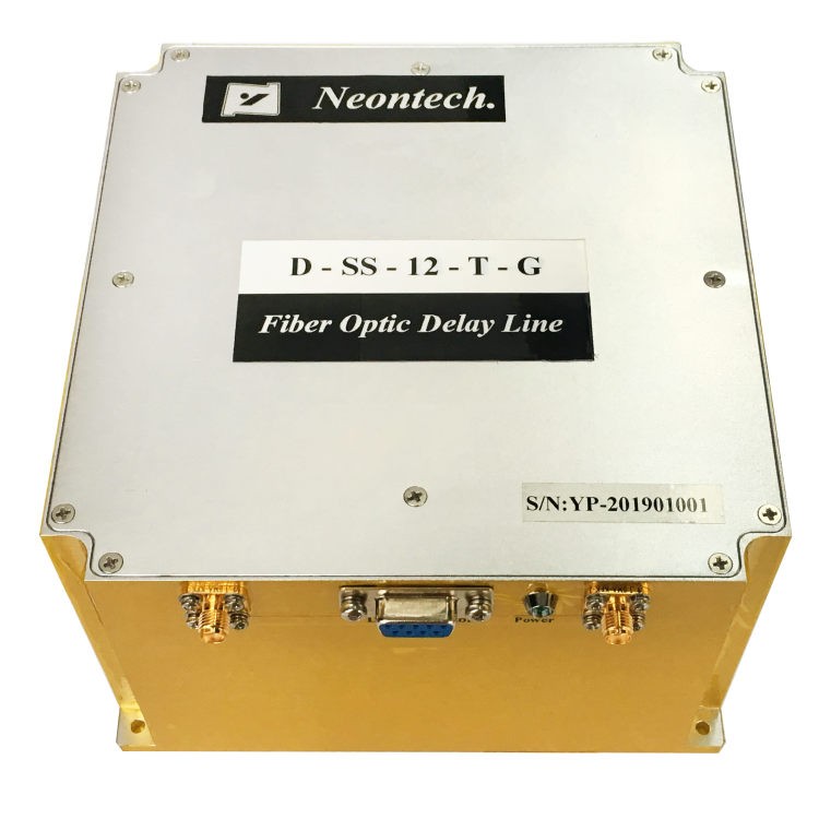
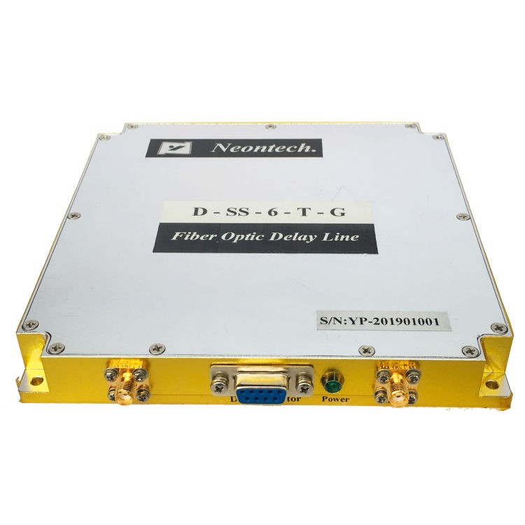
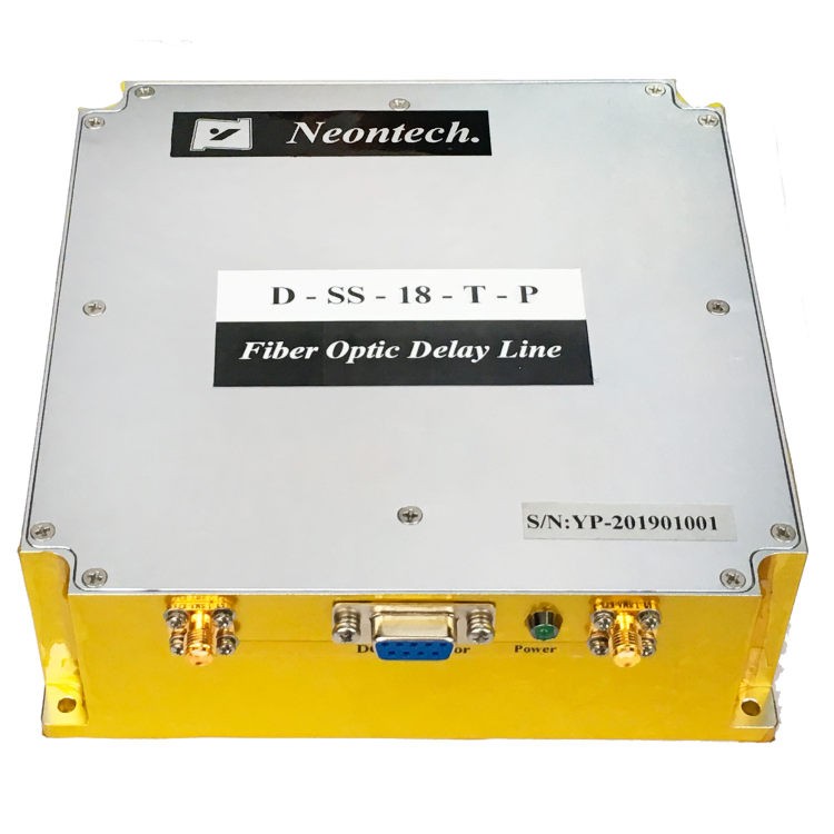
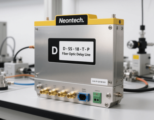
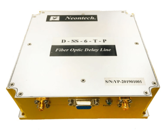
Among various products, Neon’s D-SS Series Optical Delay Line stands out as a well-balanced solution that combines ease of alignment with high performance.
This series is developed based on microwave-photonic technology and is ideal for applications such as radar testing, signal processing, phased-array antennas, antenna simulation, and phase noise measurements. Supporting full-band operation across P/L/S/C frequency bands, it offers the following advantages:
- Low insertion loss, wide dynamic range, and strong electromagnetic isolation
- Excellent performance in triple transit signals (TTS), delivering unmatched real-world accuracy
- High safety, lightweight design, compact size, high frequency capability, strong interference resistance, high precision, and wide delay range
Thanks to its compact structure and precision engineering, the alignment process is faster and more repeatable.
If you’re looking for an optical delay line that delivers outstanding performance and supports quick, reliable alignment and deployment, the D-SS Series optical delay line is undoubtedly a trusted choice.
Final Thoughts
Proper alignment of an optical delay line is critical to achieving high-performance optical control. Starting with tool preparation and setup through fine tuning and inspection, each process directly affects end system performance. Understanding proper alignment procedures not only maximizes performance in operation but also optimizes equipment life.
If you want to obtain a high-precision, easy-to-align optical delay line, feel free to reach out to Neon for technical information and bespoke solutions.


